Some people have used Quenchers, and other style spark arrestors in plasma and laser cutting applications but still experienced fires in their dust collectors. Sparks are only one issue to deal with these applications. A good spark arrestor is definitely needed to stop sparks and embers, but, it is no guarantee against fires in the dust collector.
The problem:
1. The operator may have to reset the heat setting of the plasma head. It could be generating too much atomic static particles. This causes a "painting" effect on the cartridge media, eventually clogging it.
2. Large heavy particles of molten metal can be generated in the process.
3. You should use spun bond wide pleat cartridges, to ensure proper clean out of the cartridges. That way the dust will spread over a large surface of media, instead of on the outer surface only.
4. Current cartridges that are clogging over time (can vary from hours to weeks, depending on loading). When clogging occurs, the air flow drops and sparks can slip through any spark arrestor (not just the Quencher). This sets fire to the combustible dust accumulated on the surface of the cartridges.
Normally, plasma cutters have different characteristics depending on the settings of the cutter torch. The quantity of dust produced is relatively small. At some torch settings the dust is reactive by initiating an atomic bond between the dust and the surface of the cartridge, forming a hard durable impervious coating which totally or partially plugs the filter media. This mechanism is an inherent part of the plasma coating process to put wear resistant coatings on shafts, turbine blades etc. that allow the parts to receive very long lives. In the plasma coating machinery, the key to collecting the overspray in cartridge or fabric collectors is to allow the atomic bond to dissipate. This is accomplished by extending the time that particles travel from the torch to the filter media elements. In plasma coating systems at this time, depending on torch settings will vary from 0.5 to 0.8 seconds depending on the metals being sprayed.
In plasma cutting applications often the dust being emitted from the torch does not require any special considerations. In fact, collectors can operate for many months quite well with moderate pressure drops. Then the torch settings are changed because of various factors such as the composition or thickness of the pieces that are cut. As the settings of the gun or the speed of the cut is changed, the dust can act as a plasma coating torch and the cartridges start plugging. Sparks are often produced. If the dust is combustible the sparks may ignite the coating on the cartridges. Normally the fuel on the cartridge surface is not very heavy so the fires do not damage the housing of the collector. The cartridges are then usually replaced. The QUENCHER spark arresters are sometimes applied to limit the risk of fires and extend cartridge life. In the tandem horizontal type collectors, the cartridges are usually tight spaced, so, as the pressure drop rises, the pleats are pinched in the valleys so the pressure drop goes up. Combustible dusts can put pounds of dust to be stored in the cartridges to fuel a fire in the collectors. However, the squeezing of the pleats also causes pressure drop to increase and slow the flow through the dust collector. This often allows dust to be released into the work area.
Although spark arrestors will protect the system from sparks, pieces of molten metal go through the spark arrestor unaffected. These heavy, hot particles lodge on the surface of the cartridge and ignite the combustible dust coating. The heavy molten particles need to be dropped out of the system prior to the spark arrestor and collected safely, so as not to cause a fire in that collection device. Cyclones and drop out boxes are sometimes used for this. However, be aware that these devices have little effect on sparks / embers which are light buoyant particles and slip through to the dust collector.
An excellent example of these effects was the experience of the Day division of Donaldson who supplies this design. In cutting the filter mounting plates for their design they plasma cut holes in a 1/4 inch thick plate. They found that the filters plugged quickly in the after filters. They added distance in the filters venting the operations. This experience occurred 20 years ago and we do not know how this operation is now performing.
Our recommendation is to replace the current cartridges with a wide spaced stiffened spun bond media carried and precoat the cartridges with a 1/64 inch thick coating of inert pre-coat material.
We suggest you send each job application data (layouts & pictures) to QAM technical support at gary@qamanage.com and/or call him at (519) 746-2424. We’ve dealt with plasma cutting applications for decades and feel that yours would be a common problem. If you contact us, we'll be happy to work with you on this.
For more information ... Dust collectors and dust collection solutions
Quality Air Management
Baghouse Dust Collector

Friday, May 21, 2010
Tuesday, March 30, 2010
Explosions and Fires
Part 1 – Explosions in dust collectors
Dust explosions are possible whenever the process produces combustible dusts. Not all combustible dusts will produce explosions. For instance, even combustible dusts may not have the characteristics to produce an explosion. A coarse combustible dust such as coal may burn well but not explode depending on how fine the dust is. To produce a conflagration the dust must have a sufficient ratio of surface area to weight to sustain the rapid oxidation for creating and sustaining an explosion. When a dust can sustain an explosion, the dust concentration must be within the explosive limits. These are often defined as:
L.E.L. (Lower Explosive Limit): Below this level of concentration, an explosion will not occur and propagate itself. There is not enough concentration of fuel to allow the flame front to grow. A typical range of values would be 20-30 grains/ cubic foot.
U.E.L. (Upper Explosive Limit): Above this limit the concentration of dust is so high that there is insufficient oxygen to oxidize the fuel and the unburned fuel stops the spread of the flame front.
Ignition of the dust depends on several factors
(1) Chemical Composition
(2) Shape and fineness, briefly described above.
(3) Dust distribution in the gas stream or atmosphere
(4) Concentration of oxygen in the gas stream.
(5) Initial temperature and pressure of the gas.
(6) Energy level available to detonate the explosion
Intensity of the explosion is dependent on the rate of pressure rise and maximum pressure developed. Factory Mutual ran lab tests to determine these values and are contained in their publications. It must be pointed out these tests and values are run with a spherical test chamber with power ignition source in the center of the sphere. These numbers are relatively high when referring to explosions in a dust collector housing, because the bags usually obstruct the expansion of the explosive flame front.
Limiting exposure to hazards
A) Eliminate ignition sources. One source of ignition is sparks, often produced in the hoods venting processing machines. Sometimes the machinery can be modified to prevent spark generation. Another method is to install spark suppressors prior to the dust-laden gas entering a dust collector. For sparks to be carried along to the collector the flow must be laminar. Most dust collection ductwork is deliberately designed to operate with laminar (smooth) flow to reduce pressure drop but laminar flow produces a system that is an excellent vehicle to send sparks into a dust collector. Recently, there are offered some excellent designs of spark coolers that turn laminar flow into turbulent flow for very short distances then revert back to laminar flow. These devices require pressure drops of less than one inch water column and are easily installed. An automatic self cleaning device for these spark suppressors is available.
B) Isolate Operations. The collectors may be located outdoors or away from the main production areas.
C) Introduce inerting systems. Inert dust can be introduced into the system so that the lower explosive limit of the dust mixture can be eliminated therefore the mixture will not explode. This is especially effective where the dust concentration is very low. As an example, if we have a fume dust with loading of 1 grain per thousand cubic feet of gas which is combustible, and the system has 25,000 CFM, adding an inert dust at double that load to prevent it from burning would require:
25,000 CFM x 2 gr./ 1000 CFM x 60 min./hr x 8 hrs/shift =24,000 gr./shift
24,000 gr./shift divided by7000 grains/ lb. = 3.4 lb./shift.
The other possibility is to mix the gas with another gas stream that may have the oxygen already oxidized as with a combustion process.
D) Explosion Vents can be provided on ducts and on the collector housings. These vents must be directed either outdoors or to an area where the explosion can be safely dissipated.
E) Changes in Design of collectors The collectors can be braced to withstand higher pressures so the explosion venting is more effective. Cylindrical collectors are more resistant to damage then rectangular collectors but rectangular units can be braced to withstand higher explosive pressures. Grounded bags are often supplied to drain off the static electricity charge that is a possible source of ignition. Grounded bags can provide a false sense of security to the operator and designers. Most often the dust that holds a charge insulates the static charge from the media. When the filter element is cleaned, sparks can be generated.

a) An explosion front traveling through the duct and enters the collector and dislodges the dust from the bags and then a secondary explosion occurs as the dust concentration in the housing goes between the LEL and UEL. An explosion can occur in the collector. Some methods to reduce this danger are to use smooth finish bags where residual dust on the outside of the bags is reduced. Egg shell bag finishes are a good selection. Another approach is to use laminated PTFE bags.
b) Off- line cleaning (in which the fan is shut down) increases an explosion hazard. If the collector is to be cleaned off-line with hazardous dust, the cleaning should be operated very slowly, with perhaps 3-6 minutes between pulsing a single row of bags. This will diminish the chances of the dust cloud passing through the LEL and UEL.
c) Hopper fires can occur if the hopper is not cleaned out before de-energizing the fan. These can be difficult to deal with. If a hopper door is opened an explosion can occur. There have been cases where operating personnel have tried to put out a hopper fire with a hose. The water stream agitated dust and formed a cloud of dust that passed between the LEL and UEL and the fire in the hopper provided a detonation source and serious explosions have occurred in the hopper. The best approach is to inject inert gas into the collector and allow it to cool below ignition temperatures before doing anything.
Explosion hazards in other Dust Collectors
Mechanical shaker collectors are inherently more hazardous than cylindrical bag collectors.. These collectors are cleaned off-line with no gas flow. There is always a potion of the collector which will pass through the LEL and UEL. Often the whole collector will pass through the limits during cleaning. The main approach to reducing the risk is to be careful to limit the sources of detonation when cleaning. Grounded bags are always recommended when explosive dusts are collected. Another approach is to use many small collectors instead of a central system. As discussed before, placing collectors outdoors is an option.
Pulse Jet Cartridge (Pleated filter element) Collectors are more and more of a selection in dust collector systems. When pleated filter elements were first introduced, they made the incorrect assumption that the main criterion was the filter ratio. While it is a criterion it is only one factor. A more important factor was the fact that a certain cleaning jet can only clean a fixed area of media. The rest of the area is plugged and it holds a lot of dust. This was discussed in lesson 14 (History of Cartridge Collectors). When it comes to explosion and fire hazards this plugged media contributes a lot of dust to fuel a fire or explosion if one is initiated. Some newer designs with pleated elements run at higher filter ratios and diminish the hazard by a wide margin.
Part 2; FIRES
Requirements
As we discussed above some combustible dusts, may not have a LEL in any concentration of dust in a process gas stream. However fires can occur in ducts and in a dust collector. Fires in ducts are usually a result of poor duct design so that dust drops out in ducts.
Fires can occur in exhaust ducts as well as inside dust collectors. Requirements of fires or any combustion process are: a) Fuel, in gas liquid or solid form. b) Oxygen (Atmosphere consists of 20 per cent oxygen) c) Fuel must be raised to the ignition temperature to start burning.
Sources of ignition include: Overheating of coils, motors, Friction, spontaneous combustion, static discharge, burning debris drawn into the vent system.
Spontaneous combustion occurs when dust slowly oxidizes in a collector or in any accumulated pile. The fuel oxidizes very slowly but the fuel is insulated by the dust. A “hot spot “develops. When the collector flow is resumed or the dust pile is agitated it often acts like a spark to ignite the dust (fuel).
Static discharge- Generally speaking static built up in a collector is reduced or eliminated by the jet cleaning system. The jet cleaning action dissipates most charge build up on the surface of the bags.
Burning debris drawn into the exhaust system can be a source of ignition.
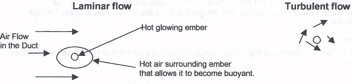
Transport of sparks through ducts. Referring to the sketch below, there is a glowing ember surrounded by some hot air which gives the sparks buoyancy. This spark and the hot gas associated with the spark can travel hundreds of feet in a duct. The ductwork is designed to give laminar (smooth ) flow. This is illustrated on the left. Spark suppressors are placed in the duct to change the flow to turbulent (coarse) flow, as shown on the right. This agitation or turbulence strips the air from around the ember removes the fuel (oxygen), therefore extinguishing and cooling the spark below ignition temperature.

For more on ... In-line spark arrestors (traps)
Prevention depends on eliminating the causes of ignition. Spark traps can change laminar to turbulent flow and extinguish any sparks in a duct. Design for proper dust transport velocities. Install pneumatic actuated duct booster to flush dust into dust collector. Use air jets to remove electrostatic charges on the duct surfaces.
For more on ... Duct cleaner - boosters
Spontaneous combustion in Pulse Jet Collectors can be prevented by pulsing the collector when the system is idle. This cools off the hot spots. For instance, brass furnace fires can be prevented by pulsing the collector every hour when the fan is not running.
Putting out fires can be accomplished by one of the following approaches: Cooling below ignition temperature, cutting off fuel supply, cutting off oxygen supply.
Water Hose and nozzles. This is an attempt to cool the solid fuels below the ignition temperature and to cut off the flow of oxygen to the fuel. It also takes away heat by turning water into steam. To boil one pound of water consumes over a 1000 BTU raising temperature of water by 200 degrees takes away less than 250 calories per pound. The steam generated can cause serious injury or death. The steam also displaces the oxygen in the air making it lethal but will often act as an inert gas to prevent oxygen from reaching the combustibles. Many dust collectors are equipped with spray nozzles. The hoppers should have automatic drains to prevent the water from doing structural damage. A 10 ft by10 ft collector with ten foot long filter bags can accumulate 40 tons of water if the sprays are not shut down or drained after the fire is extinguished.
Inert gas systems such as carbon dioxide or nitrogen gas are sometimes provided. Usually fire dampers will be provided to contain the inert gases. This will cut off the supply of oxygen to the fuel (dust and media)
Fan Operation during a Fire Whether to shut down a fan on a dust collector because of fire can be a difficult decision especially, if the collector is vented outside. Often, collectors are ignited at night and the smoke is not detected. The next morning the dust collector is virtually intact except the bags and dust have been consumed. For example a 10,000 SCFM collector removes heat at the following rate with inlet temperature of 100 deg. F. and various outlet temperatures:
OUTLET deg F. BTU/hr
150 500,000
250 1,000,000
300 2,000,000
400 3,000,000
500 4,000,000
550 4,500,000
With 1000 sq. ft. of cloth, the cloth would weigh about 100 lb and the dust about 50lb. If we assume a heat of combustion of 5,200 btu per lb, the BTU generated in a fire for this collector would be 780,000 btu. If we assume an outlet temperature of 450 degrees, it would take 30 minutes to burn itself out and the collector would probably not have damage to the tube sheet or cages. If the fan were turned off, immediately the temperatures would easily reach 1250 degrees and smolder for hours and the tube sheet and cages would be destroyed.
If the gas stream was re-circulated the decision is of course to shut down the fan.
Other fire extinguishing systems
Dust explosions are possible whenever the process produces combustible dusts. Not all combustible dusts will produce explosions. For instance, even combustible dusts may not have the characteristics to produce an explosion. A coarse combustible dust such as coal may burn well but not explode depending on how fine the dust is. To produce a conflagration the dust must have a sufficient ratio of surface area to weight to sustain the rapid oxidation for creating and sustaining an explosion. When a dust can sustain an explosion, the dust concentration must be within the explosive limits. These are often defined as:
L.E.L. (Lower Explosive Limit): Below this level of concentration, an explosion will not occur and propagate itself. There is not enough concentration of fuel to allow the flame front to grow. A typical range of values would be 20-30 grains/ cubic foot.
U.E.L. (Upper Explosive Limit): Above this limit the concentration of dust is so high that there is insufficient oxygen to oxidize the fuel and the unburned fuel stops the spread of the flame front.
Ignition of the dust depends on several factors
(1) Chemical Composition
(2) Shape and fineness, briefly described above.
(3) Dust distribution in the gas stream or atmosphere
(4) Concentration of oxygen in the gas stream.
(5) Initial temperature and pressure of the gas.
(6) Energy level available to detonate the explosion
Intensity of the explosion is dependent on the rate of pressure rise and maximum pressure developed. Factory Mutual ran lab tests to determine these values and are contained in their publications. It must be pointed out these tests and values are run with a spherical test chamber with power ignition source in the center of the sphere. These numbers are relatively high when referring to explosions in a dust collector housing, because the bags usually obstruct the expansion of the explosive flame front.
Limiting exposure to hazards
A) Eliminate ignition sources. One source of ignition is sparks, often produced in the hoods venting processing machines. Sometimes the machinery can be modified to prevent spark generation. Another method is to install spark suppressors prior to the dust-laden gas entering a dust collector. For sparks to be carried along to the collector the flow must be laminar. Most dust collection ductwork is deliberately designed to operate with laminar (smooth) flow to reduce pressure drop but laminar flow produces a system that is an excellent vehicle to send sparks into a dust collector. Recently, there are offered some excellent designs of spark coolers that turn laminar flow into turbulent flow for very short distances then revert back to laminar flow. These devices require pressure drops of less than one inch water column and are easily installed. An automatic self cleaning device for these spark suppressors is available.
B) Isolate Operations. The collectors may be located outdoors or away from the main production areas.
C) Introduce inerting systems. Inert dust can be introduced into the system so that the lower explosive limit of the dust mixture can be eliminated therefore the mixture will not explode. This is especially effective where the dust concentration is very low. As an example, if we have a fume dust with loading of 1 grain per thousand cubic feet of gas which is combustible, and the system has 25,000 CFM, adding an inert dust at double that load to prevent it from burning would require:
25,000 CFM x 2 gr./ 1000 CFM x 60 min./hr x 8 hrs/shift =24,000 gr./shift
24,000 gr./shift divided by7000 grains/ lb. = 3.4 lb./shift.
The other possibility is to mix the gas with another gas stream that may have the oxygen already oxidized as with a combustion process.
D) Explosion Vents can be provided on ducts and on the collector housings. These vents must be directed either outdoors or to an area where the explosion can be safely dissipated.
E) Changes in Design of collectors The collectors can be braced to withstand higher pressures so the explosion venting is more effective. Cylindrical collectors are more resistant to damage then rectangular collectors but rectangular units can be braced to withstand higher explosive pressures. Grounded bags are often supplied to drain off the static electricity charge that is a possible source of ignition. Grounded bags can provide a false sense of security to the operator and designers. Most often the dust that holds a charge insulates the static charge from the media. When the filter element is cleaned, sparks can be generated.
F) Changes in operation of electrical controls; Referring to figure 1, which is a view if a cylindrical bag in a Pulse jet collector.

The bag is the cylinder between the two dark hollow sections of cylinders. When the bag is cleaned a small volume of dirty air is propelled from the bags and extends a fraction of an inch between the bags. This forms a hollow cylinder of dust laden agglomerated dust. It is this hollow cylinder which is possibly between the LEL and UEL. Even if a source of ignition occurs from static charges the volume of the collector housing between these limits is usually less than 3% of the housing volume so the explosion would dissipate itself and cause no further damage. In investigating explosions in dust collection systems, there have been no verifiable explosions where the explosion was started from inside the collector from sparks while there was on line cleaning in the collector.
G) Sources of detonations In pulse jet cleaning collectors which experience explosions are as follows:a) An explosion front traveling through the duct and enters the collector and dislodges the dust from the bags and then a secondary explosion occurs as the dust concentration in the housing goes between the LEL and UEL. An explosion can occur in the collector. Some methods to reduce this danger are to use smooth finish bags where residual dust on the outside of the bags is reduced. Egg shell bag finishes are a good selection. Another approach is to use laminated PTFE bags.
b) Off- line cleaning (in which the fan is shut down) increases an explosion hazard. If the collector is to be cleaned off-line with hazardous dust, the cleaning should be operated very slowly, with perhaps 3-6 minutes between pulsing a single row of bags. This will diminish the chances of the dust cloud passing through the LEL and UEL.
c) Hopper fires can occur if the hopper is not cleaned out before de-energizing the fan. These can be difficult to deal with. If a hopper door is opened an explosion can occur. There have been cases where operating personnel have tried to put out a hopper fire with a hose. The water stream agitated dust and formed a cloud of dust that passed between the LEL and UEL and the fire in the hopper provided a detonation source and serious explosions have occurred in the hopper. The best approach is to inject inert gas into the collector and allow it to cool below ignition temperatures before doing anything.
Explosion hazards in other Dust Collectors
Mechanical shaker collectors are inherently more hazardous than cylindrical bag collectors.. These collectors are cleaned off-line with no gas flow. There is always a potion of the collector which will pass through the LEL and UEL. Often the whole collector will pass through the limits during cleaning. The main approach to reducing the risk is to be careful to limit the sources of detonation when cleaning. Grounded bags are always recommended when explosive dusts are collected. Another approach is to use many small collectors instead of a central system. As discussed before, placing collectors outdoors is an option.
Pulse Jet Cartridge (Pleated filter element) Collectors are more and more of a selection in dust collector systems. When pleated filter elements were first introduced, they made the incorrect assumption that the main criterion was the filter ratio. While it is a criterion it is only one factor. A more important factor was the fact that a certain cleaning jet can only clean a fixed area of media. The rest of the area is plugged and it holds a lot of dust. This was discussed in lesson 14 (History of Cartridge Collectors). When it comes to explosion and fire hazards this plugged media contributes a lot of dust to fuel a fire or explosion if one is initiated. Some newer designs with pleated elements run at higher filter ratios and diminish the hazard by a wide margin.
Part 2; FIRES
Requirements
As we discussed above some combustible dusts, may not have a LEL in any concentration of dust in a process gas stream. However fires can occur in ducts and in a dust collector. Fires in ducts are usually a result of poor duct design so that dust drops out in ducts.
Fires can occur in exhaust ducts as well as inside dust collectors. Requirements of fires or any combustion process are: a) Fuel, in gas liquid or solid form. b) Oxygen (Atmosphere consists of 20 per cent oxygen) c) Fuel must be raised to the ignition temperature to start burning.
Sources of ignition include: Overheating of coils, motors, Friction, spontaneous combustion, static discharge, burning debris drawn into the vent system.
Spontaneous combustion occurs when dust slowly oxidizes in a collector or in any accumulated pile. The fuel oxidizes very slowly but the fuel is insulated by the dust. A “hot spot “develops. When the collector flow is resumed or the dust pile is agitated it often acts like a spark to ignite the dust (fuel).
Static discharge- Generally speaking static built up in a collector is reduced or eliminated by the jet cleaning system. The jet cleaning action dissipates most charge build up on the surface of the bags.
Burning debris drawn into the exhaust system can be a source of ignition.
Transport of sparks through ducts. Referring to the sketch below, there is a glowing ember surrounded by some hot air which gives the sparks buoyancy. This spark and the hot gas associated with the spark can travel hundreds of feet in a duct. The ductwork is designed to give laminar (smooth ) flow. This is illustrated on the left. Spark suppressors are placed in the duct to change the flow to turbulent (coarse) flow, as shown on the right. This agitation or turbulence strips the air from around the ember removes the fuel (oxygen), therefore extinguishing and cooling the spark below ignition temperature.
For more on ... In-line spark arrestors (traps)
Prevention depends on eliminating the causes of ignition. Spark traps can change laminar to turbulent flow and extinguish any sparks in a duct. Design for proper dust transport velocities. Install pneumatic actuated duct booster to flush dust into dust collector. Use air jets to remove electrostatic charges on the duct surfaces.
For more on ... Duct cleaner - boosters
Spontaneous combustion in Pulse Jet Collectors can be prevented by pulsing the collector when the system is idle. This cools off the hot spots. For instance, brass furnace fires can be prevented by pulsing the collector every hour when the fan is not running.
Putting out fires can be accomplished by one of the following approaches: Cooling below ignition temperature, cutting off fuel supply, cutting off oxygen supply.
Water Hose and nozzles. This is an attempt to cool the solid fuels below the ignition temperature and to cut off the flow of oxygen to the fuel. It also takes away heat by turning water into steam. To boil one pound of water consumes over a 1000 BTU raising temperature of water by 200 degrees takes away less than 250 calories per pound. The steam generated can cause serious injury or death. The steam also displaces the oxygen in the air making it lethal but will often act as an inert gas to prevent oxygen from reaching the combustibles. Many dust collectors are equipped with spray nozzles. The hoppers should have automatic drains to prevent the water from doing structural damage. A 10 ft by10 ft collector with ten foot long filter bags can accumulate 40 tons of water if the sprays are not shut down or drained after the fire is extinguished.
Inert gas systems such as carbon dioxide or nitrogen gas are sometimes provided. Usually fire dampers will be provided to contain the inert gases. This will cut off the supply of oxygen to the fuel (dust and media)
Fan Operation during a Fire Whether to shut down a fan on a dust collector because of fire can be a difficult decision especially, if the collector is vented outside. Often, collectors are ignited at night and the smoke is not detected. The next morning the dust collector is virtually intact except the bags and dust have been consumed. For example a 10,000 SCFM collector removes heat at the following rate with inlet temperature of 100 deg. F. and various outlet temperatures:
OUTLET deg F. BTU/hr
150 500,000
250 1,000,000
300 2,000,000
400 3,000,000
500 4,000,000
550 4,500,000
With 1000 sq. ft. of cloth, the cloth would weigh about 100 lb and the dust about 50lb. If we assume a heat of combustion of 5,200 btu per lb, the BTU generated in a fire for this collector would be 780,000 btu. If we assume an outlet temperature of 450 degrees, it would take 30 minutes to burn itself out and the collector would probably not have damage to the tube sheet or cages. If the fan were turned off, immediately the temperatures would easily reach 1250 degrees and smolder for hours and the tube sheet and cages would be destroyed.
If the gas stream was re-circulated the decision is of course to shut down the fan.
Other fire extinguishing systems
Manual Fire extinguishers are usually either inert gas like carbon dioxide or inert powders. The gas extinguishers usually cool and put a layer of inert gas between the fuel and the flame. The manual gas extinguishers should not be operated through doors of the dust collectors as the displaced gases can be vented out through the access doors. The other manual extinguishers usually spray powder into the flames. They are not suitable to spray through access doors.
There a several other systems to fight fires in dust collectors which will not be covered in this chapter.
For more on ... Duct cleaner - boosters
Tuesday, March 23, 2010
Tandem Horizontal Cartridge Collector Design
Philosophy of design
1. Component and Fabrication costs
This line of collectors, Torit being the most popular, was developed for low initial cost, and to develop the replacement cartridge market. Donaldson has the lowest costs of production of any supplier. The replacement cartridges are at least 25% lower cost than the nearest supplier. They can sell cartridges at competitor’s costs and still have a good profit margin. With high volume customers, they use this ability to remove serious competition in a big account. For the other components such as valves and timers, they have the same advantage based on their purchase quantities. They buy in quantities of 25,000 to 50,000 and the competition buys in lots of 100-1,000.
On this line of collectors with the nominal 12 inch by 26 inch cartridge, they build the collectors in modular form so that there are two types of modules. There are two end modules and any amount of middle modules to come up with any size collector. The modules are bolted together so they match up and assembly is always the same. They can build modules in lots of 25 or more and assemble modules to make a finished collector. This lowers cost more than 35% compared to other suppliers with the same size and design collector. The modules are bolted together and they can ship collectors in two weeks with the first week devoted preparing the paper work. Since they use multiple inlets and outlets, it is hard to make a mistake in manufacturing that cannot be fixed by adding or removing modules.
2. Engineering
The holes in all of the flanges are gang punched with dies punched so they always match in spacing both for modules and hoppers. They promote their multiple hoppers to reduce engineering. The horizontal cartridge designs are designed for lowest possible headroom.
3.Shipping Costs
All assemblies are selected to be shipped with standard trucks and railroads without special permits.
Limitations of this design approach
This design requires special inlet and outlet manifolds. If cost of these manifolds are included, the cost of the system can be higher than competition. The configurations available are either right hand or left hand. Other competitive designs are more adaptable. Because of the bolted construction the tolerances between parts can produce misalignment when the cartridges are installed. One unit which we examined, which was a single cartridge instead of a tandem unit, we found that tolerances were such that the seals were not functioning. One side of the seal was bottomed and the other side was open so that dust continually leaked around the cartridge.
Capacity of cleaning system is limited by size of cleaning valve for the tandem set. This capacity is a function of the compressed air flow in the valve. As listed below the maximum filter flow rating for the tandem set is 810 CFM. The quantity of unplugged media whether fabric, cellulose or other media is also a function of valve size:
Valve size Filter flow Media Cleaned On line/off line
1/2 inch valve 360 CFM 23 sq.ft./ 28.5 sq.ft.
3/4 inch valve 810 CFM 49 sq.ft./ 61.2 sq.ft.
1 inch valve 1440 CFM 87 sq. ft./108.8 sq. ft.
1 1/2 inch 3240 CFM 193 sq ft. / 241.2 sq. ft.
Analysis of Two tandem cartridge design
This design can be analyzed as follow:
Valve: 0.75 inches to dean two cartridges
Maximum filter flow on line 810 CFM
Cartridge media area (two cartridges) 450 sq. ft.
From Table above 49 sq. ft. cleaned on line / 61.2 sq. ft. off tine
Cleaned area 49.5 sq. ft / 61 sq. ft. Plugged 400 sq. ft. / 389 sq. ft,
Cartridge weight is 40 pounds
Approximately 550 grains per sq. ft. of 60 Ib. per cu. ft. dust are collected when media is plugged. 550 gr/ sq. ft x 400 sq. ft. = 220,000 grains.
220,000 / 7000 gr./lb. = 31.5 lbs per tandem set.
Total weight of cartridge set is 40 Ib. + 31.2 Lb. = 77 Ib.
Cleaning System Actuation (Recommended)
Another factor is that the cleaning action is generally initiated by a pressure switch. The recommended prevalent pressure switch setting is about 3 1/2 inches. For most applications the pressure should be about 3/4 to 1 1/2 inches w.c. above the initial pressure drop. Typically initial pressure drop through the cartridges is 0.3 -0.5 inches of water column. Therefore, at 3 1/2 inches w.c. pressure drop, less than 17 sq. ft. of the media is available because the dust bridges across the pleats rendering the rest of the media in a condition where it cannot be cleaned by the reverse jet flow. The cartridge must be cleaned three times more frequently than if the switch were set in the proper range. This also adds about three pounds to the operating weight.
Compressed air consumption
Compressed air usage is a function of the square of the operating pressure drop. The usage is also related to the dust loading and the fineness of the dust. With a typical dust from material handling operations such as sand or rock dust and 5 grains per cu. ft., the air consumption per thousand CFM of filtered air would be as follows:
Operating Pressure drop at 85psig and 1000 CFM of filtered air
1.5 inches 0.2 SCFM
3.5 inches 1.1
4.5 inches 1.8
Filter life
The filter life is related to the cleaning frequency (or compressed air consumption) so a collector running at 1.5 inches of water will last five times as long as one running at 3.5 inches all other factors remaining the same.
Efficiency
Over 95% of the dust penetration through the filter comes immediately after each cleaning cycle. The dust penetration is related to pressure drop. With the same conditions of loading described above, the efficiency and penetration at the three pressure drops follow:
Operating pressure drop Penetration Efficiency
1.5 in. w.c. .00005 grains/cu.ft. 99.9990%
3.5 in. w.c. .00027 99.9946%
4.5 in. w.c. .00045 99.9910%
Conclusion
This design has some serious limitations, some of which can be remedied by the QAM retrofit design which will reduce pressure drop, increase efficiency and extend cartridge life.
For more information ... Retrofitting existing cartrdige dust collectors
Tuesday, November 10, 2009
Leakage From Dust Collector Outlet
Equipment: Cartridge Collector with cellulose Media, 8 pleats per inch.
Application: System designed to coat outside surfaces of gloves with starch to keep them from sticking together. It was effective and was meant for surgical use. The coating readily fell off the gloves when they were worn and before they were put to use.
Observations: The starch dust was very coarse in the 5 to 10 micron size. The dust would easily fall from the fingers when squeezed and moved together. When the system pulsed large puffs of dust were observed at the collector outlet. We examined the dust under the microscope and it was uniform in size in the 5 to 10 micron range. However, the surface of the dust particle spheres were very smooth, almost polished. The collector ran with less than one inch pressure drop across the media, the same pressure drop as a clean cartridge. The lack of the ability to interlock the dust to form a cake meant that, during pulsing, the dust would tumble and could not agglomerate and this allowed the dust to penetrate the media during and after a cleaning cycle. The collector exhaust was returned to the work space, dust and all.
Recommendations, action, remedy and conclusions.We recommended adding a small amount of ordinary cornstarch into the collector on an intermittent basis, once every four hours. This ordinary powdered (non-spheroidal) starch formed a stable filter cake and the collector ran at 2 inches of pressure drop across the media, solving the penetration problem. The contaminated starch collected from the hopper was then sold for animal consumption but it was not a significant cost for the process. Another solution was to use a standard tubular shaker collector with laminated (Gortex) media which does not require interlocking dust to form a cake.
This approach is suitable for other dusts that do not form granulated powders that don't interlock to form a cake. Another example of this kind of dust was on a process where names were engraved on plastic. There was no granulated dust. The laminated media on cylindrical bags allowed the exhaust to be re-circulated.
For assistance with such problems ... Dust Collection Solutions
Monday, November 2, 2009
Cement Plant Dust Collection
Although cement dust is relatively coarse and has optimum agglomeration properties, cement plants have some of the most demanding applications in the dust collection market.
First, all cement dust is dense and very abrasive. Even in the relatively less demanding application such as bag loading and bag unloading, these properties are important.
For many years, on the relatively light loading applications, shaker collectors were the preferred dust collectors. In fact the envelope collectors were very effective. The release of cement dust from shaker collectors was generally not a problem. In cylindrical bag collectors, the dust collected on the inside of the bag. The fastest moving air with its dust load was at the opening in the bag. There was a potential for wear near the bag entrance. If a bag developed a hole, the dust coming out of the tear would quickly abrade the surrounding bags. It seldom was possible to detect leaks until several bags, or even all the bags were damaged.
To filter a continuous process, off-line cleaning was necessary. On larger units, the collectors, in parallel sections or modules, were isolated and cleaned while maintaining flow through the remaining sections. On cement mills and other high load applications the collectors were usually preceded by cyclone pre-cleaners and the collectors often had dropout boxes or settling chambers. On these applications, shaker filters ran at filter ratios below 2:1. Air horns were often added to shaker collectors to improve cleaning and increase dust holding capacity.
In the late 60's the Fuller Corporation introduced their version of the pulse collector. This compartmented collector had large diaphragm valves that discharged into the clean air plenum. The burst of air agitated the filter bags, producing a thorough cleaning. More dust collected on a unit of filter area to allow handling of heavier dust loads. The name of this collector was "Plenum Pulse”. It was able to handle the heavier load for applications such as raw mills and finish mills. The first installations vented clinker cooler vent systems. A measure of the efficacy of this cleaning system was that the clean air plenum was built with heavier gauge metal because of weld failure with 12 gauge construction. While this collector was touted to be a pulse-jet collector, it was not. The compressed air did not create a reverse air jet. The collector operated more like a shaker than a reverse jet design. It produced more energy to clean the bags than existing shaker designs. This was especially necessary on the heavier loading processes.
Another effort to handle this high loading was the combination of shakers and reverse air cleaning systems, provided by "Norblo" a company that was based in Cleveland Ohio.
However in the late sixties, MiKroPulverizer (later renamed MikroPul) and their then licensee, FlexKleen, introduced the reverse pulsejet collectors. They were first applied to vent the raw and finish mills in the cement production process. The reverse jet collector was developed by MikroPul for their Pulverizers. These were similar to cement mills and were able to handle the heavier loads of the cement mills without pre-cleaners.
These collectors ran quite well, with filter lives exceeding three to five years. Then in 1969, when MikroPul's patent was challenged and declared invalid in court, many competitors copied their design. To counter the imitators, they made a major change in their design. The bag length went from six to ten feet. The pulse pipe orifice area was increased by the same ratio. Unfortunately, the venturi diameter was not changed. The velocity of the cleaning jet increased. It went from 15, 000 fpm to 25,000 fpm. Nobody recognized that the venturi velocity is proportional to the velocity of the dust leaving the bag towards adjoining bags during cleaning. In a dust like cement, it causes partial blinding and abrasive wear on adjoining rows during the cleaning pulse. Average pressure drops increased from 3 to 5.5 " wc. Bag lives were reduced by 50-60%. Compressed air usage went from about 0.5 SCFM per 1000 cfm of filtered air to 1.2 SCFM per 1000 cfm of filtered air. To counter these effects, the industry made some basic changes in selecting pulsejet collectors. The changes treated the symptom rather than the cause.
The development of the ULTRA-FLOW advanced technology design was able to remedy all the shortcomings of the 10 foot bag design. These designs will be discussed in future papers of this series.
Generally, the operators have chosen very conservative air to cloth ratios. Cartridge collectors are quite effective on less demanding applications.
Application Engineering Data Filter ratio - Cartridges
The belief was that more filter media (and associated filter ratio) made the selection more conservative. This idea is firmly entrenched in the cement Industry. This is generally true with pulse jet fabric collectors with high velocity cleaning jets in that it extends bag life. The fact is that the opposite is true with cartridges because of bridging across the pleats if the media is not cleaned. As dust accumulates in the valley of the pleat, it bridges. During the cleaning cycle the cleaning air looks for the easiest path from the inside to the outside of the filter cartridge. That path is above the bridge.
What contributes even more to this phenomenon is the fact that a certain volume of reverse air can only clean a certain amount of media. Because the cartridge may contain huge amounts of media that cannot be cleaned, the media not cleaned will plug. In most designs running at filter ratios of less than two, an operating cartridge may contain 10 to 40 pounds of dust. Table 1 illustrates the area of media that can be cleaned with various orifices and /or converging diverging supersonic nozzles.
Table 1
Orifice / Nozzle dia = area of media cleaned
0.250 in. = 5.5 / 8.8 sq.ft.
0.312 in. = 8.6 / 13.75 sq.ft.
0.375 in. = 12.3 / 19.8 sq.ft.
0.500 in. = 22 / 35 sq.ft.
0.750 in. = 49.5 / 79 sq.ft.
1.000 in. = 88 / 132 sq.ft.
1.500 in. = 198 / 376 sq.ft.
There are new advanced technology cartridge style dust collectors available today which incorporate wide pleat spacing, vertical cartridges and supersonic nozzles.
Dust Collector Selection
The best designs for a fabric media pulse jet collector on these applications are those offered by ULTRA-FLOW with low jet velocities and higher filter ratios The characteristics of these designs are listed below:
Find out about Ultra-Flow ... Advanced Technology Baghouse Dust Collectors
First, all cement dust is dense and very abrasive. Even in the relatively less demanding application such as bag loading and bag unloading, these properties are important.
For many years, on the relatively light loading applications, shaker collectors were the preferred dust collectors. In fact the envelope collectors were very effective. The release of cement dust from shaker collectors was generally not a problem. In cylindrical bag collectors, the dust collected on the inside of the bag. The fastest moving air with its dust load was at the opening in the bag. There was a potential for wear near the bag entrance. If a bag developed a hole, the dust coming out of the tear would quickly abrade the surrounding bags. It seldom was possible to detect leaks until several bags, or even all the bags were damaged.
To filter a continuous process, off-line cleaning was necessary. On larger units, the collectors, in parallel sections or modules, were isolated and cleaned while maintaining flow through the remaining sections. On cement mills and other high load applications the collectors were usually preceded by cyclone pre-cleaners and the collectors often had dropout boxes or settling chambers. On these applications, shaker filters ran at filter ratios below 2:1. Air horns were often added to shaker collectors to improve cleaning and increase dust holding capacity.
In the late 60's the Fuller Corporation introduced their version of the pulse collector. This compartmented collector had large diaphragm valves that discharged into the clean air plenum. The burst of air agitated the filter bags, producing a thorough cleaning. More dust collected on a unit of filter area to allow handling of heavier dust loads. The name of this collector was "Plenum Pulse”. It was able to handle the heavier load for applications such as raw mills and finish mills. The first installations vented clinker cooler vent systems. A measure of the efficacy of this cleaning system was that the clean air plenum was built with heavier gauge metal because of weld failure with 12 gauge construction. While this collector was touted to be a pulse-jet collector, it was not. The compressed air did not create a reverse air jet. The collector operated more like a shaker than a reverse jet design. It produced more energy to clean the bags than existing shaker designs. This was especially necessary on the heavier loading processes.
Another effort to handle this high loading was the combination of shakers and reverse air cleaning systems, provided by "Norblo" a company that was based in Cleveland Ohio.
However in the late sixties, MiKroPulverizer (later renamed MikroPul) and their then licensee, FlexKleen, introduced the reverse pulsejet collectors. They were first applied to vent the raw and finish mills in the cement production process. The reverse jet collector was developed by MikroPul for their Pulverizers. These were similar to cement mills and were able to handle the heavier loads of the cement mills without pre-cleaners.
These collectors ran quite well, with filter lives exceeding three to five years. Then in 1969, when MikroPul's patent was challenged and declared invalid in court, many competitors copied their design. To counter the imitators, they made a major change in their design. The bag length went from six to ten feet. The pulse pipe orifice area was increased by the same ratio. Unfortunately, the venturi diameter was not changed. The velocity of the cleaning jet increased. It went from 15, 000 fpm to 25,000 fpm. Nobody recognized that the venturi velocity is proportional to the velocity of the dust leaving the bag towards adjoining bags during cleaning. In a dust like cement, it causes partial blinding and abrasive wear on adjoining rows during the cleaning pulse. Average pressure drops increased from 3 to 5.5 " wc. Bag lives were reduced by 50-60%. Compressed air usage went from about 0.5 SCFM per 1000 cfm of filtered air to 1.2 SCFM per 1000 cfm of filtered air. To counter these effects, the industry made some basic changes in selecting pulsejet collectors. The changes treated the symptom rather than the cause.
- Filter ratios were drastically reduced. Bag life was increased and pressure drop was decreased to the 5 inch w.c. range.
- Pressure actuated cleaning systems were introduced. This kept the abrading and blinding of bags from cleaning pulses to a minimum. (The cleaning frequency and air consumption per 1000 cfm of filter air remained much higher than with the old six foot long bag designs.)
The development of the ULTRA-FLOW advanced technology design was able to remedy all the shortcomings of the 10 foot bag design. These designs will be discussed in future papers of this series.
Generally, the operators have chosen very conservative air to cloth ratios. Cartridge collectors are quite effective on less demanding applications.
Application Engineering Data Filter ratio - Cartridges
The belief was that more filter media (and associated filter ratio) made the selection more conservative. This idea is firmly entrenched in the cement Industry. This is generally true with pulse jet fabric collectors with high velocity cleaning jets in that it extends bag life. The fact is that the opposite is true with cartridges because of bridging across the pleats if the media is not cleaned. As dust accumulates in the valley of the pleat, it bridges. During the cleaning cycle the cleaning air looks for the easiest path from the inside to the outside of the filter cartridge. That path is above the bridge.
What contributes even more to this phenomenon is the fact that a certain volume of reverse air can only clean a certain amount of media. Because the cartridge may contain huge amounts of media that cannot be cleaned, the media not cleaned will plug. In most designs running at filter ratios of less than two, an operating cartridge may contain 10 to 40 pounds of dust. Table 1 illustrates the area of media that can be cleaned with various orifices and /or converging diverging supersonic nozzles.
Table 1
Orifice / Nozzle dia = area of media cleaned
0.250 in. = 5.5 / 8.8 sq.ft.
0.312 in. = 8.6 / 13.75 sq.ft.
0.375 in. = 12.3 / 19.8 sq.ft.
0.500 in. = 22 / 35 sq.ft.
0.750 in. = 49.5 / 79 sq.ft.
1.000 in. = 88 / 132 sq.ft.
1.500 in. = 198 / 376 sq.ft.
There are new advanced technology cartridge style dust collectors available today which incorporate wide pleat spacing, vertical cartridges and supersonic nozzles.
Dust Collector Selection
The best designs for a fabric media pulse jet collector on these applications are those offered by ULTRA-FLOW with low jet velocities and higher filter ratios The characteristics of these designs are listed below:
- Average velocity at bag opening = 10,000 feet per minute
- Bag opening (no venturi) = 4" diameter
- Jet volume = 740 CFM
- Bag diameter and length = 4 inches x 96 inches
- Bag area = 10 sq. ft.
- Filter volume rating per bag = 190 CFM
- Nominal filter ratio = 20 FPM
- Average pressure drop = 2 1/2 inches water column
- Average Air Consumption = 1/2 SCFM/1000 CFM of flow
- Average dust penetration at 5 gr./cu. ft. load = 0.0005 gr. / cu. ft.
Find out about Ultra-Flow ... Advanced Technology Baghouse Dust Collectors
Monday, June 15, 2009
Condensation in Dust Collectors
Let's look at three service reports which illustrate the problems of condensation and outline the possible solutions.
London, Ontario Installation;
Cartridge Dust collector retrofit on Plasma cutting stations
The client complained of having to service the cartridges every 1-2 days because they would plug up. The pressure drop across the collector would rise to 8-10 inches water column. The cleaning system was totally redesigned, and six 36” high ratio style cartridge filters replaced twenty-four 26” tandem cartridges. 80/20 paper blend cartridges were installed temporarily until special anti-pinch style polyester filters could be supplied. Within two days the paper cartridges blew apart, mostly at the closed end-cap. They did run the pulsed cleaning system at 100psi instead of 85psi, with no regulator on the line. However, that was not enough to rip the media apart, so, something else was the cause. Upon inspection of the cartridges, we observed that the media was dry but had the look of being wetted. Also there were watermark stains on the clean side of the media. There was an accumulator tank on the compressed air line leading to the collector. The maintenance people told us the accumulator was installed because the valve manifold wasn’t large enough to hold enough residual pressure during a pulse. The manifold was just fine. What was happening is that the air line was very long (over 200 feet) from the compressor to the collector. Moisture would condense in the line then drop out at two elbows, which was the low point just before going up to the manifold. This choked the line which made the manifold appear like it was too small, and then suddenly a slug of water would blow through to the valves and into the cartridges. We recommended taking out the accumulator tank and, just before the connection to the valve manifold, installing an air line coalescing filter, top quality dryer, and a regulator set for 85psi. We also recommended an automatic drain valve system on the manifold tank. The collector now runs continuously at 3-3.5inch pressure drop. The client says they’ve never been able to control the contaminants at the plasma stations so well since they installed the system 1.5 years prior to the retrofit.
Maine Installation; Energy Recovery from Trash and garbage.
This collector installation was venting a large room where garbage was dumped. Front-end loaders took this garbage and carried it to the hoppers that fed an incinerator. Steam was produced that fed a boiler. The pulse jet collector vented 65,000 ACFM at ambient conditions. It was running at a 15:1 filter ratio and at 2 “ water column from January to June. In June the pressure drop started to creep upwards about 1/8 of inch per week. This collector was well instrumented with continuous recording of wet bulb and dry bulb temperatures as well as pressure drop. We compared the pressure drop increases with the weather reports in the local newspapers. The increases occurred early in the morning on days when the wet bulb and dry bulb temperature were closer than 5 degrees F. There were several kinds of trash being handled in the facility. We recommended that they not load the wet trash into the incinerator until after 10:00 a.m. This stopped the rising pressure drop problem. Since they shut the system down on weekends we recommended that they clean the collector for two hours on Saturday afternoon with the outlet fan damper 90% closed. This was almost as effective as off line cleaning and the dust was not blown back into the loading room during the procedure. The dust collector ran for at least two years, at less than three inches water gauge pressure drop after implementing these recommendations.
General Comments The cleaning system was running at 85 psig. Under typical conditions the compressed air expands to critical pressure which is 37psig. beyond this pressure, the pressure to velocity conversion stops and from 37 psig to atmospheric pressure, 0 psig, the energy is turned to heat from turbulence. This nullifies the refrigeration cycle as the compressed air expands to critical pressure. This collector used converging diverging nozzles which had a complete conversion of pressure to energy so that the refrigeration cycle was reducing the temperature in the jet by approximately 5-8 degrees F.
Actually the turbulence below 37 psig causes some heat regain but the jet is still 5-8 degrees cooler despite this. Without the regain it would be about 9-12 degrees cooler. With a converging diverging nozzles the amount of cooling from expanded compressed air in the jet is a bit colder but the amount of induced air from the plenum is almost twice as much as with an ordinary orifice so the jet temperature is about 6-8 degrees cooler but not enough to make a difference. In Maine, the problem was mainly in the summer when the trash was wet from people dumping beer and other associated liquids. They did not have the problem in the winter when the trash was dry.
There were two other approaches that could have been used to counter the rising pressure drop:
1) Larger pulse valves and eliminating the nozzles. However, this would increase air consumption by over 35%.
2) Manifold heaters could be installed that would raise the temperature of the cleaning jet above ambient even to the point where wet garbage could be processed in high humidity conditions.
In either case, the collector could not handle vent volume where the gas entering the collector has condensed water droplets.
Low pressure compressed air, in the range of 7 to 22 psig is often employed for pulse jet cleaning systems. These have the same effect as the cleaning system with converging diverging nozzles since no turbulence occurs as complete expansion occurs in the orifice or nozzle. The best remedies are as follows:
1. Locate the low pressure compressor near the pulse valves and insulate the manifold leading to the pulse valves.
2. Use a manifold heater in the compressed air header, same as described above.
Other Comments and observations. There are many other installations in energy recovery plants that use high ratio reverse air fan collectors, The temperature regain on the reverse air fan is higher than ambient and eliminates condensation considerations described above.
East Tennessee Installation; Powder coating
This plant in the upper elevations in the mountains used a pulse jet collector to vent a powder coating operation that coated the internals of residential wash machines. This pulse jet collector started in July and ran until the middle of the winter when it developed a creeping rise in pressure drop characteristics. The wet and dry bulb spread was usually over 15 degrees F except early in the morning when it was about ten degrees. Investigation of the operation was conducted and we measured wet and dry bulb temperatures with a sling psychrometer mounted through a hole in the main vent duct. What we discovered is the booths were manually washed with a hot water hose every morning. At times the gas would go through the dew point for several minutes and then immediately go back to operation at a wide dew point spread. We recommended mounting a heater with a damper on a branch line to the vent system. The heater was triggered by pressure switches on the hot water hoses in each booth. This eliminated the creeping pressure drop problem permanently.
For information ... Dust Collector retrofits and Troubleshooting
Thursday, February 19, 2009
Static Electricity and Dust Collector Systems
General Considerations
The effects of static electricity on the collection of dry particulate in fabric collectors is rather simple but misunderstood. For the most part, cartridge dust collectors experience the same issues.
First we must consider the cause of static charge build up in a collector. It occurs because the dust being collected is akin to a capacitor in an electronic circuit. In this day of computer chips the designer may not be familiar with this phenomenon. The capacity has two conductive plates separated by a layer of insulating material that has high enough insulation values that the static charge remains for relatively long periods. The charge can be removed by grounding one side of the capacitor. The charges then drain.
In dust collectors where the dust forms in the filter cake, the static charges may enter the collector on the surface of dry particulate dust. If the dust has high dielectric resistance properties, it can accumulate and build up in the filter cake. It can be viewed as many particles each carrying a static charge and acting like a miniature capacitor. The static charge will then build up on the surfaces and may reach a high enough level where a spark can be produced. This spark can trigger the explosion of explosive dusts.
Mechanical Cleaning (Shaker) Dust Collectors
In a fabric collector with a mechanical shaking mechanism to remove the dust, the collector is most vulnerable during the cleaning process. The dust is shaken from the filter bags in the process of shaking the cake, sparks sometimes are produced. Invariably, the dust/ gas mixture passes between the upper and lower explosive limits. A serious explosion may occur.
Usually these collectors will have explosion vents which relieve the high pressures that are generated in an explosion, presumably keeping the housing from being damaged and protecting the operating personnel near the dust collector.
In an attempt to keep this static charge from building to threatening levels, measures are included in an attempt to bleed this charge to ground. These include one or more of the following:
1) Sewing in grounding wires into the filter media.
2) Impregnating carbon or other conductive coating into the filter cloth.
These often give the designer a false sense of security in applying these to dust collectors. As explained above the dust, itself, insulates the charge and it remains in the cake until it reaches a point where a spark is generated. If the dust concentration is above the lower explosive limit and below the upper explosive limit, an explosion can occur. Fortunately, generation of the spark may not occur if the timing of the spark and dust concentration level do not coincide. An explosion does not occur in these cases.
Continuous Cleaning Reverse Jet Pulsed Dust Collectors
When dust, with the same properties described above, is vented in the same operations, using a reverse pulse jet cleaning system, the danger is considerably diminished unless the pulsing is applied in “off line” cleaning mode where the fan is stopped.
These collectors clean the bags by injecting air from the clean air plenum backwards through individual bags as the flow continues through the collector. This cleaning agitates the filter cake so the static charges are dissipated.
The danger of explosion occurs when the dust concentration coming into the collector reaches a level between the lower and upper explosive limit concentrations. This is highly unlikely but we recommend that properly sized explosion vents are installed which normally coincides with the requirements of insurance underwriting firms.
The explosions can occur when there is dust build up in ducts especially when long horizontal runs are encountered. The spark can be generated in ducts and the explosion front can travel down the duct into the dust collector, igniting a secondary explosion as the concentration in the collector housing is driven above the lower explosive limit for that dust. Even with no build up in the ductwork, an upset can occur in the process which generates sufficient dust concentrations.
One method of nullifying the possibilities of danger due to duct build up is to install an automatic booster / duct cleaner device. This booster can serve to automatically clean out any drop out in long horizontal duct runs.
Another phenomenon can affect of dust collector systems, is where the dust has high dielectric properties and the dust, because of static charges, will build up on the outside bend of an elbow. This dust can trigger an explosion if this dust is also flammable and explosive. Some examples of dust where this problem is often a factor are toners for copy machines and electrolyte powder used in alkaline batteries. The solution is to insert a pulsed air jet that agitates the built up dust that dissipates the charge. Some dry powder coating compounds are also subject to static charge build up in powder coating systems.
Read more about ... Booster / Duct Cleaner, and Quencher spark arrestor
Subscribe to:
Posts (Atom)