The problem was that humidity and water was plugging the bags and accumulating in the collector & ducts. We depended on information that we got from the customer. We looked at the furnaces and they looked pretty standard. We asked them about the operation. What kind of salts they were using in the molten salt vats. We were told Barium Chloride. Most of the rest of the discussion then was about the existing dust collector. We suggested that the chief problem of corrosion was that moisture was condensing on the wall since the collector was located outdoors. They agreed that was probably correct. We discussed the possibility of locating the collector inside. We said we could do this because of the high ratio advanced technology style of dust collector used.
At no time was the subject of continuous seeding with limestone discussed. They did discuss that the collector had been operating for several years and were running at six inches pressure drop. That is normal for MAC collector designs. From our view, this was consistent with other furnaces that we knew had fabric collectors venting quench furnaces with molten salts of Barium Chloride or Sodium Chloride (standard salt like you have in a salt shaker).
They told us that they had been working with a representative from a well known cartridge dust collector supplier. They showed us sketches of some wooden hoods that they built to determine volume including temperatures in the hoods. These hoods were close coupled to the molten surfaces and they wanted us to bid that type of hood, which was unlike the ones that were already in place. They said they wanted us to bid cartridge collectors but we had never heard of a single installation on these quench operations. The temperatures that they measured were close to 200 degrees F and that was problematic, however the cloth bags of a baghouse could withstand 275 degrees. We would not bid a cartridge collector at those temperatures. There was no doubt that they were impressed with Donaldson and all the work they had done together on this project.
We did not specifically ask about Calcium chloride. There are various salts applied in these heat treating furnaces. Normally, when Calcium chloride is used they install water wash scrubbers. At American Air Filter, our colleague ran the scrubber department and they sold more than a hundred scrubbers that were venting either sodium chloride or calcium chloride heat treating operations. From the discussion, no “red flags" were raised and we judged this as a low risk application.
We assumed someone else went to the site to make measurements and lay out the ducts and fan since we never made any measurements. Next thing we heard that the cartridge dust collector was a lower price than our dust collector. We told the client that a cartridge collector could not work. We asked them to go back to the supplier and find a place where cartridge collectors had been applied on this type application. As it turned out they could not find a single place where they had applied a cartridge collector on salt bath quench operations. As a result they gave us the order.
After we installed the equipment there were complaints of water in the system. We were absolutely surprised since we were sure the wall temperatures were much higher than the dew point of the process air. We were sure that our design kept any condensation from the process gas stream. The operation could not produce moisture from feeding parts into the bath since wet parts would cause an explosion in the molten baths and might injure workers in the area.
We got samples of the salts. Six of the bottles were Barium Chloride and two bottles were labeled Heat Treat Mixture XX. It looked like the Calcium chloride salts that we used to melt ice since the salt was in the form of spheres 1/8 inch in diameter. The heat quench salt supplier told us that it was Calcium Chloride. They were reluctant to send more information so we ran the tests in our oven. We determined that the barium chloride was stable from 50 degrees up to 180 degrees F.
The calcium chloride would absorb water vapor and was a desiccant. How much and how fast the vapor was turned to liquid depended on the relative humidity and temperature. For instance, at 80 degrees and 80% humidity the liquid would not appear for more than twenty minutes. At 100 degrees and 50% humidity, it took several hours. Air flowing across the calcium chloride speeded the reaction but we had no equipment to measure the values. We found out the reaction would stop at 130 degrees F and higher. If the liquid formed it would take temperatures of over 160OF to dry out the calcium chloride.
We installed heaters in the ducts. Unfortunately, when the new bags were installed, the volume through the system went up and the heaters only increased the temperature to 110 from the previous reading of 105, We fed some baking soda into the collector to neutralize the calcium chloride but It was not enough to stop the formation of the water. It is obvious that the reactant must be fed continuously since it looks like the soda gets pulsed off before the end of the day and when the collector is shut down water is formed and plugs the bags.
This is an example of getting into trouble when we are not given all the information especially after the system was installed. We are competent but not magicians. The cartridge collector would not have lasted two weeks even with lime feed. We continuously shot ourselves in the leg on this project:
1) When we were installing the hoods, they insisted we move the hoods back at least six inches because they wanted access to a thermocouple opening. This meant that we would have more cold air blowing in and the exhaust temperature would be lower. Looking at it from hindsight this was the beginning of a lot of trouble. From the expected 200 degrees we were now at 110. At the time it seemed OK, since we were unaware of the calcium chloride. We should have insisted they move the location of the thermocouple probe instead, but we never suspected temperature was a problem. At the time we figured cooler is better.
2) Because the hood was moved back, this indicated we had to use the narrow high hoods to capture the fume instead of the squat ones close to the vats. The further away from the furnace, the higher the hood must be. These higher hoods drew in even more cooler air and the temperature dropped to near 100.
3) We put in heaters but they were sized wrong. Our sales rep had the same view that we originally had that the problem was with the water condensing on the walls and ducts. All he needed was to raise the temperature by 20 degrees and we would be home free. He figured that the higher volume after the bags were changed would further raise the temperature to the collector. The temperature coming from the duct venting the calcium chloride bath was 180 degrees, but most the reaction always had taken place on the bags. Between that and the insulated ducts he judged that the problem was solved. If engineering had selected the heaters, we would have designed them for 165 degree entrance temperature to the collector. When we visited after the heaters were installed. I was a bit surprised. Besides the client was complaining about the $2,400 they had to pay to wire the heaters. We measured the current in the heaters. It was about 25% of what I was expecting. The wrong heater was installed
Here we must not lose sight that the problem is related to the desiccant properties. We now needed to try to extricate ourselves from this mess that would allow us to look reasonably competent.
A) The most obvious approach is to put in a feed system to feed sodium carbonate to the system especially at the end of the shift. It looks like the pressure climbs overnight. It was not known if the collector runs all night. They probably do it more than one way. We believe they shut the fan off over the weekend and continue pulsing. That is probably the worst thing that they can do.
B) We might put a damper on the fan and cut the flow back when they are not operating so duct heaters heat the air to the collector to 160 degrees. This would dry out the calcium chloride and allow it to be removed from the collector.
C) We might put a big heater on the duct from the third hood that does not have a heater.
For help with ... Fixing existing jobs or designing new dust collection applications
Read more about ... Most advanced technology dust collectors
Quality Air Management
Baghouse Dust Collector

Monday, November 8, 2010
Tuesday, October 5, 2010
Plasma Cutting & Cartridges
This is the result from using our cartridge and fabric filter element inspection service.
1) It was not the cartridge that was normally supplied to clients.
2) It had an inverted cone reinforcement in the bottom closed end cap. We always recommend a flat closed end cap for maximum life. The pleat spacing was optimum for this kind of application.
3) The seals (gasket) were resilient which insures effective sealing between the clean air and dirty air compartments. The cartridge exhibited no evidence of improper installation or handling.
4) You could expect indefinite life on this filter element on all suitable applications with an advanced technology pulse jet cleaning system like ULTRA-FLOW.
This plasma cutting operation is quite common and we see many cartridges with problems from these operations. The dust generated is extremely fine and problems with seals and installation account for a big majority of problems. The other problem, that we see is that the settings on the cutting head are such that the dust can be prone to plasma coat the filter elements. The solution of the coating problem is to give the dust time to lose its reactivity before it reaches the filter media. None of these usual problems were evident on this filter element.
A) My first observation was the color of the coating on the filter. In cutting ferrous metal with a plasma arc cutter, the dust is black and coated with fine easily removed powder. In handling of these filter elements, we usually wear a mask because of the fine dust generated in the inspection process. In this case there was no dust generated in the procedure. The color of the coating was brown.
B) My second observation was that there was hard inflexible crust covering the dirty side of the pleats as if the element had been painted. It had the same strength as baked on auto finish.
C) The only time I previously observed this kind of coating on a cutting operation was when the plates were covered with some kind of coolant, cutting oil or pickled. On some cutters they use compressed air at the head. I would suggest checking the air line lubricant as a possible source of the binder that is creating this paint like coating.
Finally, a continuous coating of filter aid could be maintained on the surface of the filter media. The dust load is usually quite light and the coating might be about a 64th thick. The surface coating would be painted instead of the media. When the collector pulses the inert filter aid, coated with the paint, would be ejected into the collection hopper. How often to clean would be a judgment call. I would expect the cleaning and re coating every 2- 4 hours would be appropriate.
Read more ... Retrofit Service for Cartridge Dust Collectors
Find out about ... Most Advanced Technology Dust Collectors
Wednesday, August 25, 2010
Compare Spark Arrestors
Spark Arrestors; and Spark Coolers
(A comparison of different methods)
There are several approaches to the issue of extinguishing sparks in a gas stream.
Important Factors in Spark Arrestor Selection
Blender Type Air Mixers
A number of these air blender/mixers have been applied with varied success as in-line spark coolers, arrestors and suppressors. Over the last several years standard air mixers have been adapted and applied between the spark generating process and dust collector. They were applied in processes where fires in the dust collectors had previously occurred. One supplier hired a consultant to develop a market for these air blender/mixers as a spark arrestor/cooler. This air blending or mixer style design was an outgrowth of mixing two gas streams of different temperatures to insure a uniform temperature after the static mixer. It was deduced that the gas stream produced turbulent flow as it passed through the blades and this was the reason it could be adapted to spark cooling. However, these are air mixers first and spark arrestors second. They are marketed as having low pressure drop (maximum 0.5 inch WC) through them. There are performance limitations because not enough turbulence (and related pressure drop) is imparted to the spark/ember. To achieve spark suppression, we need to go from laminar to highly turbulent flow in the duct which strips away the hot air envelope around the spark/ember thereby cooling it and starving it of fuel (oxygen). For air blending this is not a requirement. Also, these devices have large gaps between the mixing blades, when looking through the inlet and downstream of the device. These gaps can allow a percentage of sparks/embers to slip through and cause a fire or even an explosion in the dust collector.
Improved In-Line Spark Arrestors
QAM developed the QUENCHER, which is a variation of the blender/mixer design. It is also an in-line spark arrestor. Employing a 60 year old spin vane mist eliminator technology developed by Sly Manufacturing in the early 1960’s, led QAM to vary the blade designs to have the most effective performance, inducing maximum turbulence to the gas stream, and lowering the cost. Maximum turbulence (and the pressure drop that results from it) is the key to spark arresting. After several tests it was found that the air blending/mixer design did not impart enough turbulence and some sparks got through, especially at low gas stream velocities. Eventually, there was a specific design which imparted the most effective swirling and turbulence thereby extinguishing the sparks quickly and most effectively. In fact, during testing of the QUENCHER, the arrestor cell would light up as a ball of fire, however, one inch past the cell nothing was left in the gas stream. These designs were incorporated into the QUENCHER. QAM has developed special application data in which the blade angles are adjusted to produce minimum effective pressure drop for different temperatures and gas densities. To our knowledge, no one else accounts for the gas density effects on spark arrestors. In truth, due to the advanced design, even applying the incorrect parameters to a QUENCHER may not result in a failure to put out sparks. Since the pressure drop across the device are a function of the velocity through it, the development of a pneumatically operated booster was introduced to prevent dust dropout accumulating in the static arresting cell. It also blows out accumulations on the blades.
Find out more ... Quencher spark arrestor
Liquid Spray Systems
For many years these systems were the only method to prevent fires caused by sparks. The system consists of electronic detectors that detect sparks and react to their presence. When a spark is detected liquid sprays are actuated and water sprayed into the duct. The sprays actually cool the gas stream below the dew point. However, in dust collection systems, the water then wets the filter bags or cartridges. This prevents fires but the gas flow is interrupted and the bags must be either replaced or dried out before the process can resume. It takes a whole day or two to dry out the bags or even to prevent blinding and replacement. The detector sensitivity can be lowered to prevent excessive actuations, but, this reduces the reliability of the systems. The detector missing a spark is an ever present danger and a fire may occur. Bag or cartridge replacement is definitely required.
Cyclone Dust Collectors
Contrary to common belief cyclones are not effective spark arrestors. For a spark arrestor / cooler to work, there must be high turbulence in the air stream. If you have turbulence in a cyclone the pressure drop is very high. Cyclones are designed to avoid turbulence. Many bag house fires occur in systems with cyclone pre-cleaners. Amazingly the inlet baffles on the baghouse are more effective as spark arrestors, however they are not foolproof.
Static Blade Spark Suppressor (Tri Pass)
These were developed in Japan to replace multiple cyclones in coal fired boilers. They found that the multiple cyclones did not stop sparks from entering the dust collectors. The first ones were installed in the early 1970’s. They ran at 1.5 inches of pressure drop and were fabricated from structural angles to resist the wear of the abrasive ashes in the coal that they fired. There are several of these applications installed in the USA and Canada designed by one of our colleagues.
Static Baffle-Box Spark Arrestor
Many dust collector suppliers offer this type of device as a spark arrestor. It consists of air entering at one end of a baffle box running over a baffle plate which drops out the sparks and much of the dust collected. The air exits at the other end, and then travels to the dust collector. The big drawback is that a hopper and flexible or solid hose connection to a collection barrel is required. Also, these devices do not eliminate all of the sparks. There is not enough turbulence generated to ensure 100% spark arresting. Sparks may also ignite the contents of the collection bin under it.
Mesh Filters
This is a common stop-gap measure where the filter is placed at the exhaust duct of hoods or installed in the ductwork. When clean, the mesh filter will stop at best 80% of sparks. These filters do not produce enough pressure drop to be fully effective. It only takes one spark to ignite dust in the duct or set a dust collector on fire. The only thing these filters do is clog up and add to your maintenance.
We trust that the above information will enable you to evaluate and select the most suitable method and supplier for your application. Buying our QUENCHER/BOOSTER spark arrestor combination will give you a risk free unit, fine tuned for each application.
See our engineering bulletin ... "Compare Spark Arresting Methods" (PDF)
(A comparison of different methods)
There are several approaches to the issue of extinguishing sparks in a gas stream.
Important Factors in Spark Arrestor Selection
- There is no such thing as an efficiency rating for spark arrestors. They either work or they don’t. Remember, it takes only one spark/ember getting through the device to cause a fire or explosion.
- Maximum turbulence is the key to effective spark arresting and in the selection of a spark arresting device. Some devices do not impart enough turbulence (and/or pressure drop) to be 100% effective. The recommended pressure drop for an in-line device (one that is installed in a section of the ductwork) is between 0.75 and 1.5 inches WC. Anything less is highly risky. This is a basic law of physics.
- Pressure drop across a QUENCHER style of spark arrestor is a function of the Reynolds number which is proportional to the density for air. This means that a unit can be sized smaller if operating at a higher temperature. For instance a spark arrestor operating at 440 degrees F is 2/3 the size of the typical unit applied at 70 degrees F and the pressure drop will be designed the same. This lowers the cost of the spark arrestor and ensures its effectiveness. The density is also affected by the water vapor in the gas stream. It has little effect at temperatures below 125oF but can be a major factor when operating at higher temperatures.
- If the gas stream has dust that might drop out in the duct at the velocities in the blender style or QUENCHER spark arrestor, a booster must be provided to periodically remove this accumulation. If this unit is not kept clean, it might pose a threat by putting an extra load on the ductwork. Without an automatic duct cleaner-booster system, the spark arrestor would require periodic manual cleaning.
- The duct cleaner - booster design is also temperature sensitive and must be altered to accommodate changing gas stream conditions.
- Most suppliers do not have the capability to modify the designs as referred to in item (3), (4), (5) above.
Blender Type Air Mixers
A number of these air blender/mixers have been applied with varied success as in-line spark coolers, arrestors and suppressors. Over the last several years standard air mixers have been adapted and applied between the spark generating process and dust collector. They were applied in processes where fires in the dust collectors had previously occurred. One supplier hired a consultant to develop a market for these air blender/mixers as a spark arrestor/cooler. This air blending or mixer style design was an outgrowth of mixing two gas streams of different temperatures to insure a uniform temperature after the static mixer. It was deduced that the gas stream produced turbulent flow as it passed through the blades and this was the reason it could be adapted to spark cooling. However, these are air mixers first and spark arrestors second. They are marketed as having low pressure drop (maximum 0.5 inch WC) through them. There are performance limitations because not enough turbulence (and related pressure drop) is imparted to the spark/ember. To achieve spark suppression, we need to go from laminar to highly turbulent flow in the duct which strips away the hot air envelope around the spark/ember thereby cooling it and starving it of fuel (oxygen). For air blending this is not a requirement. Also, these devices have large gaps between the mixing blades, when looking through the inlet and downstream of the device. These gaps can allow a percentage of sparks/embers to slip through and cause a fire or even an explosion in the dust collector.
Improved In-Line Spark Arrestors
QAM developed the QUENCHER, which is a variation of the blender/mixer design. It is also an in-line spark arrestor. Employing a 60 year old spin vane mist eliminator technology developed by Sly Manufacturing in the early 1960’s, led QAM to vary the blade designs to have the most effective performance, inducing maximum turbulence to the gas stream, and lowering the cost. Maximum turbulence (and the pressure drop that results from it) is the key to spark arresting. After several tests it was found that the air blending/mixer design did not impart enough turbulence and some sparks got through, especially at low gas stream velocities. Eventually, there was a specific design which imparted the most effective swirling and turbulence thereby extinguishing the sparks quickly and most effectively. In fact, during testing of the QUENCHER, the arrestor cell would light up as a ball of fire, however, one inch past the cell nothing was left in the gas stream. These designs were incorporated into the QUENCHER. QAM has developed special application data in which the blade angles are adjusted to produce minimum effective pressure drop for different temperatures and gas densities. To our knowledge, no one else accounts for the gas density effects on spark arrestors. In truth, due to the advanced design, even applying the incorrect parameters to a QUENCHER may not result in a failure to put out sparks. Since the pressure drop across the device are a function of the velocity through it, the development of a pneumatically operated booster was introduced to prevent dust dropout accumulating in the static arresting cell. It also blows out accumulations on the blades.
Find out more ... Quencher spark arrestor
Liquid Spray Systems
For many years these systems were the only method to prevent fires caused by sparks. The system consists of electronic detectors that detect sparks and react to their presence. When a spark is detected liquid sprays are actuated and water sprayed into the duct. The sprays actually cool the gas stream below the dew point. However, in dust collection systems, the water then wets the filter bags or cartridges. This prevents fires but the gas flow is interrupted and the bags must be either replaced or dried out before the process can resume. It takes a whole day or two to dry out the bags or even to prevent blinding and replacement. The detector sensitivity can be lowered to prevent excessive actuations, but, this reduces the reliability of the systems. The detector missing a spark is an ever present danger and a fire may occur. Bag or cartridge replacement is definitely required.
Cyclone Dust Collectors
Contrary to common belief cyclones are not effective spark arrestors. For a spark arrestor / cooler to work, there must be high turbulence in the air stream. If you have turbulence in a cyclone the pressure drop is very high. Cyclones are designed to avoid turbulence. Many bag house fires occur in systems with cyclone pre-cleaners. Amazingly the inlet baffles on the baghouse are more effective as spark arrestors, however they are not foolproof.
Static Blade Spark Suppressor (Tri Pass)
These were developed in Japan to replace multiple cyclones in coal fired boilers. They found that the multiple cyclones did not stop sparks from entering the dust collectors. The first ones were installed in the early 1970’s. They ran at 1.5 inches of pressure drop and were fabricated from structural angles to resist the wear of the abrasive ashes in the coal that they fired. There are several of these applications installed in the USA and Canada designed by one of our colleagues.
Static Baffle-Box Spark Arrestor
Many dust collector suppliers offer this type of device as a spark arrestor. It consists of air entering at one end of a baffle box running over a baffle plate which drops out the sparks and much of the dust collected. The air exits at the other end, and then travels to the dust collector. The big drawback is that a hopper and flexible or solid hose connection to a collection barrel is required. Also, these devices do not eliminate all of the sparks. There is not enough turbulence generated to ensure 100% spark arresting. Sparks may also ignite the contents of the collection bin under it.
Mesh Filters
This is a common stop-gap measure where the filter is placed at the exhaust duct of hoods or installed in the ductwork. When clean, the mesh filter will stop at best 80% of sparks. These filters do not produce enough pressure drop to be fully effective. It only takes one spark to ignite dust in the duct or set a dust collector on fire. The only thing these filters do is clog up and add to your maintenance.
We trust that the above information will enable you to evaluate and select the most suitable method and supplier for your application. Buying our QUENCHER/BOOSTER spark arrestor combination will give you a risk free unit, fine tuned for each application.
See our engineering bulletin ... "Compare Spark Arresting Methods" (PDF)
Monday, July 12, 2010
Wet Collector Underperformance
Equipment:
C5-2500, orifice scrubber style wet dust collector, rated for 2500 CFM, purchased to handle explosive aluminum dust particles.
Problem:
The dust was going right through the collector and packing into the fan / outlet compartment. Very little dust was collected in the dust collector sump.
Investigation and observations:
We requested pictures and system layout drawings (sketches were actually provided). From these we observed that the client did not describe the application accurately at the time of purchase.
1. The dust was produced from a spray coating operation. Therefore, it was fine powder type aluminum dust. Wet collectors are designed for metal dust 5 microns and larger, as generated from grinding and cutting operations.
2. The inlet was connected to a properly sized 8” duct but was over 20 feet long with three elbows. These units are designed for maximum 10 feet of duct directly to the collection point.
3. The client also decided to exhaust the discharge of the collector to the outdoors with another 20-25 feet of duct, and three more elbows. These collectors are designed for an open, unrestricted discharge on the top of the unit.
The result of this was a questionable capability of collecting the powder type dust. The biggest problem was that the collector performance was choked by far too much resistance to airflow in the installation. By doing this the air entered the collector with far too little volume to cause the necessary turbulent energy in the “omega” style baffles. The necessary wetting action of the dust particles was not taking place and filtering action was non-existent.
Solution:
1. We asked the client to place some of the collected dust in a closed jar with water. Then shake it and let it sit for a few minutes. If the dust settles, it can be collected. If it doesn’t, a different dust collection solution must be found.
2. A wet dust collector is very particular about the airflow through it. You need to be in a range of +/_ 10% of the rated CFM for that model dust collector. In this case, the minimum flow that could be tolerated is 2250 CFM. Conversely, with more than flow than the 10%, water gets drawn up too much and discharges out the unit. We recommended bringing the collector closer to the application and remove the duct on the outlet. Alternatively, add a booster fan to overcome the restriction.
Other Considerations:
A. If the excess resitriction is minor (within the 10% range) but dust is discharging at the top, You would add more water to the collector, in small increments, until the dust/water stops coming out the top. The added water compensates for the higher restriction. Then reset the float control to maintain this new water level.
B. In some cases the discharge is required to be exhausted by code. An example is beryllium. In such a case, do not attach a duct on the outlet. Instead build a capture hood over the top of the wet collector outlet, approximately 4-6 above the top, and duct that to the outside. Install a fan to give you 5-10% more air flow than what is running through the collector, to ensure no contaminents escape back into the room.
C. If you oversized the wet collector, Do not restrict the flow with a damper more than the 10% tolerance. Install a bleed-in on the inlet duct with an adjustable shut-off damper. Open the damper to the point where the collector performs properly. This is often a scenario when you size the collector for multiple collection points but don’t have them all installed until later.
Need help? ... System trouble-shooting
Friday, June 18, 2010
Explosion Vents
This is a touchy topic and greatly misunderstood. Today, plant operators recognize that there is more danger from lawyers, on this issue, than from actual explosions in the dust collector. In fact, the accumulation of dust in the plant itself is a greater danger for conflagration than a properly engineered dust collection system. Go to our website and view the videos on “Combustible dust in the workplace” by 60 Minutes on CBS and the U.S. Chemical Safety and Hazard Investigation Board.
Go to view .... Combustible dust videos
Explosions in Dust Collectors
Explosions in pulse jet collectors invariably are when cleaning off-line and can be prevented by sound practice. We run into a risky process when we write the safe procedure because it is application dependent and relies on common sense of the operators. If your design is good engineering, there will be no explosion. All explosions in pulse jet dust collectors, we have investigated (about 100 or so), have been clear cut stupidity. Among the typical ones; horseplay, ignoring warnings posted on equipment and disgruntled employee sabotage.
The most risky application is a mechanical cleaning (shaker style) dust collector when cleaned off-line, and, you can only clean them off-line. A dangerous spark is generated by static charges produced during the shaker action. If I were there, I would tell someone else to turn off the collector or put a long delay on the shaker actuator while I go to the restroom. There is no particular reason to warrant us to observe an explosion first hand. I am cowardly since I heal from injuries slowly.
Advanced Technology vs Poorly Designed Dust Collectors
An overwhelming number of explosions have occurred on badly designed collectors with bottom inlets in which the fine dust has difficulty in making its way to the hopper until the fan is shut down. Advanced technology dust collectors (such as ULTRA-FLOW), with their high side inlet and high ratio cleaning system, have some marked advantages that further reduce the risks involved in explosions. One major advantage is the extremely high efficiency of these designs which prevents dust being returned to the plant, thereby reducing the hazard of accumulated dust referred to the introductory paragraph of this bulletin. The cleaning system more thoroughly cleans the bags and the inventory of dust on the bags is very low, and usually not sufficient to cause the dust concentration to go above the lower explosive limit in the event of an explosion front traveling into the collector from the inlet ducts. With these collectors, the fire and explosion generally occurs outside the collector, in the ductwork, and is drawn into the collector. In normal operation there is only a very small part of the collector that passes through the lower explosive limit. This consists of a narrow band about 1/8 to 1/4 inches thick that surrounds the bag when it is cleaned. Eggshell or singed finishes on the filter bag is recommended to further reduce dust inventory on the bags.
Placing the explosion vent below the filters (i.e. in the hopper) is a bad idea. It allows the pressure to build up in the housing before it can be released by an undersized vent in the hopper. This is especially true with conventional dust collector designs that have venturis restricting the neck of the filter cage at the tube-sheet. With advanced technology designs (having no venturi), we have 12-15 times more open area to the outlet which in itself is a natural explosion vent. We place the vent in the housing side where it offers the most protection by venting the explosion immediately where it occurs.
Woodworking
Because of the NFPA rules do not directly apply to dust collectors, there is much latitude in their interpretation. The solution is to apply sound engineering to assess the risk and to provide equipment suitable for a particular service. Venting woodworking applications is probably the largest number of installations in the dust collector industry. Explosions have occurred and the venting has been quite effective in controlling them.
The norm in the industry, for the last 30 or so years, has been to provide a 60:1 vent ratio. This has been sufficient for this service. ULTRA-FLOW uses a standard 20:1 vent ratio for its explosion vents, which further protects against the harmful effects of an explosion.
Vent Ratio
This was developed by UL labs. It is the ratio of the volume of the dirty air compartment of a dust collector to the area of the explosion vent. For example; a cylindrical bag dust collector with (24) 6 inch by 6 foot bags, dirty air housing size of 6ft x 4ft x 6ft, hopper which is 1/3 x ( 6 x 4 x6 ). The gross volume of the collector = 192 cu.ft. The volume of the bags is 24 x 1.2 cu.ft./ bag = 28.2. The volume of the collector = 192 – 28.2 = 164 cu.ft. Therefore, if we want a vent ratio of 20:1; 164/20 = 8 sq.ft. of explosion vent.
Ultra-Flow dust collectors use a vent ratio of 20:1. In general the insurance companies determine the specification that they want and we supply it accordingly. In the end, good engineering is the key.
Kst Ratings
This issue is very complex and not as easy as just meeting a “Kst” deflagration rating. It is an NFPA 68 test requirement for ideal lab conditions. “Kst” refers to the rate of pressure rise in an explosion. Unfortunately defining of the number is difficult since NFPA never really measure it except when they use a sealed globe enclosure, stir the dust in it and then try to ignite it with a sparkplug. This is not the real world of dust collectors.
A more accurate test was performed by AAF specifically on dust collectors. See the “Combustible Dusts” chart at the end of this bulletin. That chart shows the “Explosion Pressure” or burst pressure where theoretically a dust collector will blow apart in an explosion. If a dust collector is built of 12 gage steel to withstand +/- 20 SP (inWG). The burst pressure is usually a factor of 4 times that or 80 psi. As an example, for wood dust it was determined that a vent ratio of only 180:1 was safe in a dust collector. The chart says the burst pressure would be 35psi which is less than the 80psi allowed. Ultra-Flow uses a 20:1 vent ratio, therefore it is 9 times that value, so, you are as safe as you can get. No matter what you do, there will always be some risk. All we can do is make it inconsequential. As mentioned above, there is a far greater risk from dust in the plant than you will find in the dust collector itself. Look on the home page of our website for the news reports on “Combustible Dusts in the workplace”.
Read more ... Explosion Venting
Friday, May 21, 2010
Plasma/Laser Cutters Cause Fires
Some people have used Quenchers, and other style spark arrestors in plasma and laser cutting applications but still experienced fires in their dust collectors. Sparks are only one issue to deal with these applications. A good spark arrestor is definitely needed to stop sparks and embers, but, it is no guarantee against fires in the dust collector.
The problem:
1. The operator may have to reset the heat setting of the plasma head. It could be generating too much atomic static particles. This causes a "painting" effect on the cartridge media, eventually clogging it.
2. Large heavy particles of molten metal can be generated in the process.
3. You should use spun bond wide pleat cartridges, to ensure proper clean out of the cartridges. That way the dust will spread over a large surface of media, instead of on the outer surface only.
4. Current cartridges that are clogging over time (can vary from hours to weeks, depending on loading). When clogging occurs, the air flow drops and sparks can slip through any spark arrestor (not just the Quencher). This sets fire to the combustible dust accumulated on the surface of the cartridges.
Normally, plasma cutters have different characteristics depending on the settings of the cutter torch. The quantity of dust produced is relatively small. At some torch settings the dust is reactive by initiating an atomic bond between the dust and the surface of the cartridge, forming a hard durable impervious coating which totally or partially plugs the filter media. This mechanism is an inherent part of the plasma coating process to put wear resistant coatings on shafts, turbine blades etc. that allow the parts to receive very long lives. In the plasma coating machinery, the key to collecting the overspray in cartridge or fabric collectors is to allow the atomic bond to dissipate. This is accomplished by extending the time that particles travel from the torch to the filter media elements. In plasma coating systems at this time, depending on torch settings will vary from 0.5 to 0.8 seconds depending on the metals being sprayed.
In plasma cutting applications often the dust being emitted from the torch does not require any special considerations. In fact, collectors can operate for many months quite well with moderate pressure drops. Then the torch settings are changed because of various factors such as the composition or thickness of the pieces that are cut. As the settings of the gun or the speed of the cut is changed, the dust can act as a plasma coating torch and the cartridges start plugging. Sparks are often produced. If the dust is combustible the sparks may ignite the coating on the cartridges. Normally the fuel on the cartridge surface is not very heavy so the fires do not damage the housing of the collector. The cartridges are then usually replaced. The QUENCHER spark arresters are sometimes applied to limit the risk of fires and extend cartridge life. In the tandem horizontal type collectors, the cartridges are usually tight spaced, so, as the pressure drop rises, the pleats are pinched in the valleys so the pressure drop goes up. Combustible dusts can put pounds of dust to be stored in the cartridges to fuel a fire in the collectors. However, the squeezing of the pleats also causes pressure drop to increase and slow the flow through the dust collector. This often allows dust to be released into the work area.
Although spark arrestors will protect the system from sparks, pieces of molten metal go through the spark arrestor unaffected. These heavy, hot particles lodge on the surface of the cartridge and ignite the combustible dust coating. The heavy molten particles need to be dropped out of the system prior to the spark arrestor and collected safely, so as not to cause a fire in that collection device. Cyclones and drop out boxes are sometimes used for this. However, be aware that these devices have little effect on sparks / embers which are light buoyant particles and slip through to the dust collector.
An excellent example of these effects was the experience of the Day division of Donaldson who supplies this design. In cutting the filter mounting plates for their design they plasma cut holes in a 1/4 inch thick plate. They found that the filters plugged quickly in the after filters. They added distance in the filters venting the operations. This experience occurred 20 years ago and we do not know how this operation is now performing.
Our recommendation is to replace the current cartridges with a wide spaced stiffened spun bond media carried and precoat the cartridges with a 1/64 inch thick coating of inert pre-coat material.
We suggest you send each job application data (layouts & pictures) to QAM technical support at gary@qamanage.com and/or call him at (519) 746-2424. We’ve dealt with plasma cutting applications for decades and feel that yours would be a common problem. If you contact us, we'll be happy to work with you on this.
For more information ... Dust collectors and dust collection solutions
Tuesday, March 30, 2010
Explosions and Fires
Part 1 – Explosions in dust collectors
Dust explosions are possible whenever the process produces combustible dusts. Not all combustible dusts will produce explosions. For instance, even combustible dusts may not have the characteristics to produce an explosion. A coarse combustible dust such as coal may burn well but not explode depending on how fine the dust is. To produce a conflagration the dust must have a sufficient ratio of surface area to weight to sustain the rapid oxidation for creating and sustaining an explosion. When a dust can sustain an explosion, the dust concentration must be within the explosive limits. These are often defined as:
L.E.L. (Lower Explosive Limit): Below this level of concentration, an explosion will not occur and propagate itself. There is not enough concentration of fuel to allow the flame front to grow. A typical range of values would be 20-30 grains/ cubic foot.
U.E.L. (Upper Explosive Limit): Above this limit the concentration of dust is so high that there is insufficient oxygen to oxidize the fuel and the unburned fuel stops the spread of the flame front.
Ignition of the dust depends on several factors
(1) Chemical Composition
(2) Shape and fineness, briefly described above.
(3) Dust distribution in the gas stream or atmosphere
(4) Concentration of oxygen in the gas stream.
(5) Initial temperature and pressure of the gas.
(6) Energy level available to detonate the explosion
Intensity of the explosion is dependent on the rate of pressure rise and maximum pressure developed. Factory Mutual ran lab tests to determine these values and are contained in their publications. It must be pointed out these tests and values are run with a spherical test chamber with power ignition source in the center of the sphere. These numbers are relatively high when referring to explosions in a dust collector housing, because the bags usually obstruct the expansion of the explosive flame front.
Limiting exposure to hazards
A) Eliminate ignition sources. One source of ignition is sparks, often produced in the hoods venting processing machines. Sometimes the machinery can be modified to prevent spark generation. Another method is to install spark suppressors prior to the dust-laden gas entering a dust collector. For sparks to be carried along to the collector the flow must be laminar. Most dust collection ductwork is deliberately designed to operate with laminar (smooth) flow to reduce pressure drop but laminar flow produces a system that is an excellent vehicle to send sparks into a dust collector. Recently, there are offered some excellent designs of spark coolers that turn laminar flow into turbulent flow for very short distances then revert back to laminar flow. These devices require pressure drops of less than one inch water column and are easily installed. An automatic self cleaning device for these spark suppressors is available.
B) Isolate Operations. The collectors may be located outdoors or away from the main production areas.
C) Introduce inerting systems. Inert dust can be introduced into the system so that the lower explosive limit of the dust mixture can be eliminated therefore the mixture will not explode. This is especially effective where the dust concentration is very low. As an example, if we have a fume dust with loading of 1 grain per thousand cubic feet of gas which is combustible, and the system has 25,000 CFM, adding an inert dust at double that load to prevent it from burning would require:
25,000 CFM x 2 gr./ 1000 CFM x 60 min./hr x 8 hrs/shift =24,000 gr./shift
24,000 gr./shift divided by7000 grains/ lb. = 3.4 lb./shift.
The other possibility is to mix the gas with another gas stream that may have the oxygen already oxidized as with a combustion process.
D) Explosion Vents can be provided on ducts and on the collector housings. These vents must be directed either outdoors or to an area where the explosion can be safely dissipated.
E) Changes in Design of collectors The collectors can be braced to withstand higher pressures so the explosion venting is more effective. Cylindrical collectors are more resistant to damage then rectangular collectors but rectangular units can be braced to withstand higher explosive pressures. Grounded bags are often supplied to drain off the static electricity charge that is a possible source of ignition. Grounded bags can provide a false sense of security to the operator and designers. Most often the dust that holds a charge insulates the static charge from the media. When the filter element is cleaned, sparks can be generated.

a) An explosion front traveling through the duct and enters the collector and dislodges the dust from the bags and then a secondary explosion occurs as the dust concentration in the housing goes between the LEL and UEL. An explosion can occur in the collector. Some methods to reduce this danger are to use smooth finish bags where residual dust on the outside of the bags is reduced. Egg shell bag finishes are a good selection. Another approach is to use laminated PTFE bags.
b) Off- line cleaning (in which the fan is shut down) increases an explosion hazard. If the collector is to be cleaned off-line with hazardous dust, the cleaning should be operated very slowly, with perhaps 3-6 minutes between pulsing a single row of bags. This will diminish the chances of the dust cloud passing through the LEL and UEL.
c) Hopper fires can occur if the hopper is not cleaned out before de-energizing the fan. These can be difficult to deal with. If a hopper door is opened an explosion can occur. There have been cases where operating personnel have tried to put out a hopper fire with a hose. The water stream agitated dust and formed a cloud of dust that passed between the LEL and UEL and the fire in the hopper provided a detonation source and serious explosions have occurred in the hopper. The best approach is to inject inert gas into the collector and allow it to cool below ignition temperatures before doing anything.
Explosion hazards in other Dust Collectors
Mechanical shaker collectors are inherently more hazardous than cylindrical bag collectors.. These collectors are cleaned off-line with no gas flow. There is always a potion of the collector which will pass through the LEL and UEL. Often the whole collector will pass through the limits during cleaning. The main approach to reducing the risk is to be careful to limit the sources of detonation when cleaning. Grounded bags are always recommended when explosive dusts are collected. Another approach is to use many small collectors instead of a central system. As discussed before, placing collectors outdoors is an option.
Pulse Jet Cartridge (Pleated filter element) Collectors are more and more of a selection in dust collector systems. When pleated filter elements were first introduced, they made the incorrect assumption that the main criterion was the filter ratio. While it is a criterion it is only one factor. A more important factor was the fact that a certain cleaning jet can only clean a fixed area of media. The rest of the area is plugged and it holds a lot of dust. This was discussed in lesson 14 (History of Cartridge Collectors). When it comes to explosion and fire hazards this plugged media contributes a lot of dust to fuel a fire or explosion if one is initiated. Some newer designs with pleated elements run at higher filter ratios and diminish the hazard by a wide margin.
Part 2; FIRES
Requirements
As we discussed above some combustible dusts, may not have a LEL in any concentration of dust in a process gas stream. However fires can occur in ducts and in a dust collector. Fires in ducts are usually a result of poor duct design so that dust drops out in ducts.
Fires can occur in exhaust ducts as well as inside dust collectors. Requirements of fires or any combustion process are: a) Fuel, in gas liquid or solid form. b) Oxygen (Atmosphere consists of 20 per cent oxygen) c) Fuel must be raised to the ignition temperature to start burning.
Sources of ignition include: Overheating of coils, motors, Friction, spontaneous combustion, static discharge, burning debris drawn into the vent system.
Spontaneous combustion occurs when dust slowly oxidizes in a collector or in any accumulated pile. The fuel oxidizes very slowly but the fuel is insulated by the dust. A “hot spot “develops. When the collector flow is resumed or the dust pile is agitated it often acts like a spark to ignite the dust (fuel).
Static discharge- Generally speaking static built up in a collector is reduced or eliminated by the jet cleaning system. The jet cleaning action dissipates most charge build up on the surface of the bags.
Burning debris drawn into the exhaust system can be a source of ignition.
Transport of sparks through ducts. Referring to the sketch below, there is a glowing ember surrounded by some hot air which gives the sparks buoyancy. This spark and the hot gas associated with the spark can travel hundreds of feet in a duct. The ductwork is designed to give laminar (smooth ) flow. This is illustrated on the left. Spark suppressors are placed in the duct to change the flow to turbulent (coarse) flow, as shown on the right. This agitation or turbulence strips the air from around the ember removes the fuel (oxygen), therefore extinguishing and cooling the spark below ignition temperature.

For more on ... In-line spark arrestors (traps)
Prevention depends on eliminating the causes of ignition. Spark traps can change laminar to turbulent flow and extinguish any sparks in a duct. Design for proper dust transport velocities. Install pneumatic actuated duct booster to flush dust into dust collector. Use air jets to remove electrostatic charges on the duct surfaces.
For more on ... Duct cleaner - boosters
Spontaneous combustion in Pulse Jet Collectors can be prevented by pulsing the collector when the system is idle. This cools off the hot spots. For instance, brass furnace fires can be prevented by pulsing the collector every hour when the fan is not running.
Putting out fires can be accomplished by one of the following approaches: Cooling below ignition temperature, cutting off fuel supply, cutting off oxygen supply.
Water Hose and nozzles. This is an attempt to cool the solid fuels below the ignition temperature and to cut off the flow of oxygen to the fuel. It also takes away heat by turning water into steam. To boil one pound of water consumes over a 1000 BTU raising temperature of water by 200 degrees takes away less than 250 calories per pound. The steam generated can cause serious injury or death. The steam also displaces the oxygen in the air making it lethal but will often act as an inert gas to prevent oxygen from reaching the combustibles. Many dust collectors are equipped with spray nozzles. The hoppers should have automatic drains to prevent the water from doing structural damage. A 10 ft by10 ft collector with ten foot long filter bags can accumulate 40 tons of water if the sprays are not shut down or drained after the fire is extinguished.
Inert gas systems such as carbon dioxide or nitrogen gas are sometimes provided. Usually fire dampers will be provided to contain the inert gases. This will cut off the supply of oxygen to the fuel (dust and media)
Fan Operation during a Fire Whether to shut down a fan on a dust collector because of fire can be a difficult decision especially, if the collector is vented outside. Often, collectors are ignited at night and the smoke is not detected. The next morning the dust collector is virtually intact except the bags and dust have been consumed. For example a 10,000 SCFM collector removes heat at the following rate with inlet temperature of 100 deg. F. and various outlet temperatures:
OUTLET deg F. BTU/hr
150 500,000
250 1,000,000
300 2,000,000
400 3,000,000
500 4,000,000
550 4,500,000
With 1000 sq. ft. of cloth, the cloth would weigh about 100 lb and the dust about 50lb. If we assume a heat of combustion of 5,200 btu per lb, the BTU generated in a fire for this collector would be 780,000 btu. If we assume an outlet temperature of 450 degrees, it would take 30 minutes to burn itself out and the collector would probably not have damage to the tube sheet or cages. If the fan were turned off, immediately the temperatures would easily reach 1250 degrees and smolder for hours and the tube sheet and cages would be destroyed.
If the gas stream was re-circulated the decision is of course to shut down the fan.
Other fire extinguishing systems
Dust explosions are possible whenever the process produces combustible dusts. Not all combustible dusts will produce explosions. For instance, even combustible dusts may not have the characteristics to produce an explosion. A coarse combustible dust such as coal may burn well but not explode depending on how fine the dust is. To produce a conflagration the dust must have a sufficient ratio of surface area to weight to sustain the rapid oxidation for creating and sustaining an explosion. When a dust can sustain an explosion, the dust concentration must be within the explosive limits. These are often defined as:
L.E.L. (Lower Explosive Limit): Below this level of concentration, an explosion will not occur and propagate itself. There is not enough concentration of fuel to allow the flame front to grow. A typical range of values would be 20-30 grains/ cubic foot.
U.E.L. (Upper Explosive Limit): Above this limit the concentration of dust is so high that there is insufficient oxygen to oxidize the fuel and the unburned fuel stops the spread of the flame front.
Ignition of the dust depends on several factors
(1) Chemical Composition
(2) Shape and fineness, briefly described above.
(3) Dust distribution in the gas stream or atmosphere
(4) Concentration of oxygen in the gas stream.
(5) Initial temperature and pressure of the gas.
(6) Energy level available to detonate the explosion
Intensity of the explosion is dependent on the rate of pressure rise and maximum pressure developed. Factory Mutual ran lab tests to determine these values and are contained in their publications. It must be pointed out these tests and values are run with a spherical test chamber with power ignition source in the center of the sphere. These numbers are relatively high when referring to explosions in a dust collector housing, because the bags usually obstruct the expansion of the explosive flame front.
Limiting exposure to hazards
A) Eliminate ignition sources. One source of ignition is sparks, often produced in the hoods venting processing machines. Sometimes the machinery can be modified to prevent spark generation. Another method is to install spark suppressors prior to the dust-laden gas entering a dust collector. For sparks to be carried along to the collector the flow must be laminar. Most dust collection ductwork is deliberately designed to operate with laminar (smooth) flow to reduce pressure drop but laminar flow produces a system that is an excellent vehicle to send sparks into a dust collector. Recently, there are offered some excellent designs of spark coolers that turn laminar flow into turbulent flow for very short distances then revert back to laminar flow. These devices require pressure drops of less than one inch water column and are easily installed. An automatic self cleaning device for these spark suppressors is available.
B) Isolate Operations. The collectors may be located outdoors or away from the main production areas.
C) Introduce inerting systems. Inert dust can be introduced into the system so that the lower explosive limit of the dust mixture can be eliminated therefore the mixture will not explode. This is especially effective where the dust concentration is very low. As an example, if we have a fume dust with loading of 1 grain per thousand cubic feet of gas which is combustible, and the system has 25,000 CFM, adding an inert dust at double that load to prevent it from burning would require:
25,000 CFM x 2 gr./ 1000 CFM x 60 min./hr x 8 hrs/shift =24,000 gr./shift
24,000 gr./shift divided by7000 grains/ lb. = 3.4 lb./shift.
The other possibility is to mix the gas with another gas stream that may have the oxygen already oxidized as with a combustion process.
D) Explosion Vents can be provided on ducts and on the collector housings. These vents must be directed either outdoors or to an area where the explosion can be safely dissipated.
E) Changes in Design of collectors The collectors can be braced to withstand higher pressures so the explosion venting is more effective. Cylindrical collectors are more resistant to damage then rectangular collectors but rectangular units can be braced to withstand higher explosive pressures. Grounded bags are often supplied to drain off the static electricity charge that is a possible source of ignition. Grounded bags can provide a false sense of security to the operator and designers. Most often the dust that holds a charge insulates the static charge from the media. When the filter element is cleaned, sparks can be generated.
F) Changes in operation of electrical controls; Referring to figure 1, which is a view if a cylindrical bag in a Pulse jet collector.

The bag is the cylinder between the two dark hollow sections of cylinders. When the bag is cleaned a small volume of dirty air is propelled from the bags and extends a fraction of an inch between the bags. This forms a hollow cylinder of dust laden agglomerated dust. It is this hollow cylinder which is possibly between the LEL and UEL. Even if a source of ignition occurs from static charges the volume of the collector housing between these limits is usually less than 3% of the housing volume so the explosion would dissipate itself and cause no further damage. In investigating explosions in dust collection systems, there have been no verifiable explosions where the explosion was started from inside the collector from sparks while there was on line cleaning in the collector.
G) Sources of detonations In pulse jet cleaning collectors which experience explosions are as follows:a) An explosion front traveling through the duct and enters the collector and dislodges the dust from the bags and then a secondary explosion occurs as the dust concentration in the housing goes between the LEL and UEL. An explosion can occur in the collector. Some methods to reduce this danger are to use smooth finish bags where residual dust on the outside of the bags is reduced. Egg shell bag finishes are a good selection. Another approach is to use laminated PTFE bags.
b) Off- line cleaning (in which the fan is shut down) increases an explosion hazard. If the collector is to be cleaned off-line with hazardous dust, the cleaning should be operated very slowly, with perhaps 3-6 minutes between pulsing a single row of bags. This will diminish the chances of the dust cloud passing through the LEL and UEL.
c) Hopper fires can occur if the hopper is not cleaned out before de-energizing the fan. These can be difficult to deal with. If a hopper door is opened an explosion can occur. There have been cases where operating personnel have tried to put out a hopper fire with a hose. The water stream agitated dust and formed a cloud of dust that passed between the LEL and UEL and the fire in the hopper provided a detonation source and serious explosions have occurred in the hopper. The best approach is to inject inert gas into the collector and allow it to cool below ignition temperatures before doing anything.
Explosion hazards in other Dust Collectors
Mechanical shaker collectors are inherently more hazardous than cylindrical bag collectors.. These collectors are cleaned off-line with no gas flow. There is always a potion of the collector which will pass through the LEL and UEL. Often the whole collector will pass through the limits during cleaning. The main approach to reducing the risk is to be careful to limit the sources of detonation when cleaning. Grounded bags are always recommended when explosive dusts are collected. Another approach is to use many small collectors instead of a central system. As discussed before, placing collectors outdoors is an option.
Pulse Jet Cartridge (Pleated filter element) Collectors are more and more of a selection in dust collector systems. When pleated filter elements were first introduced, they made the incorrect assumption that the main criterion was the filter ratio. While it is a criterion it is only one factor. A more important factor was the fact that a certain cleaning jet can only clean a fixed area of media. The rest of the area is plugged and it holds a lot of dust. This was discussed in lesson 14 (History of Cartridge Collectors). When it comes to explosion and fire hazards this plugged media contributes a lot of dust to fuel a fire or explosion if one is initiated. Some newer designs with pleated elements run at higher filter ratios and diminish the hazard by a wide margin.
Part 2; FIRES
Requirements
As we discussed above some combustible dusts, may not have a LEL in any concentration of dust in a process gas stream. However fires can occur in ducts and in a dust collector. Fires in ducts are usually a result of poor duct design so that dust drops out in ducts.
Fires can occur in exhaust ducts as well as inside dust collectors. Requirements of fires or any combustion process are: a) Fuel, in gas liquid or solid form. b) Oxygen (Atmosphere consists of 20 per cent oxygen) c) Fuel must be raised to the ignition temperature to start burning.
Sources of ignition include: Overheating of coils, motors, Friction, spontaneous combustion, static discharge, burning debris drawn into the vent system.
Spontaneous combustion occurs when dust slowly oxidizes in a collector or in any accumulated pile. The fuel oxidizes very slowly but the fuel is insulated by the dust. A “hot spot “develops. When the collector flow is resumed or the dust pile is agitated it often acts like a spark to ignite the dust (fuel).
Static discharge- Generally speaking static built up in a collector is reduced or eliminated by the jet cleaning system. The jet cleaning action dissipates most charge build up on the surface of the bags.
Burning debris drawn into the exhaust system can be a source of ignition.
Transport of sparks through ducts. Referring to the sketch below, there is a glowing ember surrounded by some hot air which gives the sparks buoyancy. This spark and the hot gas associated with the spark can travel hundreds of feet in a duct. The ductwork is designed to give laminar (smooth ) flow. This is illustrated on the left. Spark suppressors are placed in the duct to change the flow to turbulent (coarse) flow, as shown on the right. This agitation or turbulence strips the air from around the ember removes the fuel (oxygen), therefore extinguishing and cooling the spark below ignition temperature.
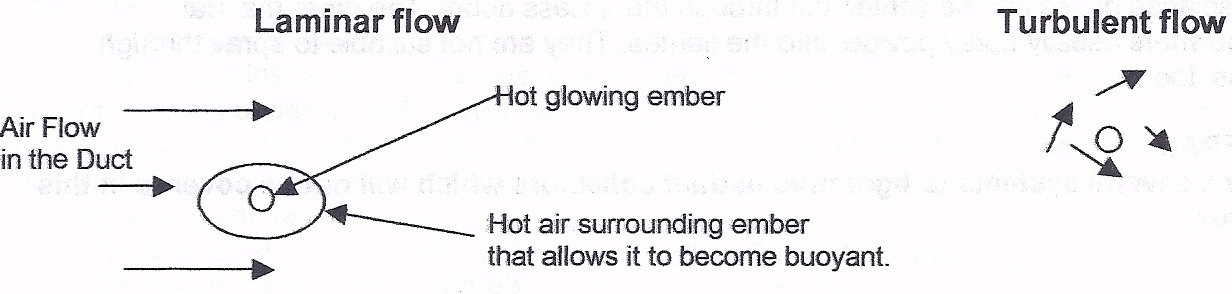
For more on ... In-line spark arrestors (traps)
Prevention depends on eliminating the causes of ignition. Spark traps can change laminar to turbulent flow and extinguish any sparks in a duct. Design for proper dust transport velocities. Install pneumatic actuated duct booster to flush dust into dust collector. Use air jets to remove electrostatic charges on the duct surfaces.
For more on ... Duct cleaner - boosters
Spontaneous combustion in Pulse Jet Collectors can be prevented by pulsing the collector when the system is idle. This cools off the hot spots. For instance, brass furnace fires can be prevented by pulsing the collector every hour when the fan is not running.
Putting out fires can be accomplished by one of the following approaches: Cooling below ignition temperature, cutting off fuel supply, cutting off oxygen supply.
Water Hose and nozzles. This is an attempt to cool the solid fuels below the ignition temperature and to cut off the flow of oxygen to the fuel. It also takes away heat by turning water into steam. To boil one pound of water consumes over a 1000 BTU raising temperature of water by 200 degrees takes away less than 250 calories per pound. The steam generated can cause serious injury or death. The steam also displaces the oxygen in the air making it lethal but will often act as an inert gas to prevent oxygen from reaching the combustibles. Many dust collectors are equipped with spray nozzles. The hoppers should have automatic drains to prevent the water from doing structural damage. A 10 ft by10 ft collector with ten foot long filter bags can accumulate 40 tons of water if the sprays are not shut down or drained after the fire is extinguished.
Inert gas systems such as carbon dioxide or nitrogen gas are sometimes provided. Usually fire dampers will be provided to contain the inert gases. This will cut off the supply of oxygen to the fuel (dust and media)
Fan Operation during a Fire Whether to shut down a fan on a dust collector because of fire can be a difficult decision especially, if the collector is vented outside. Often, collectors are ignited at night and the smoke is not detected. The next morning the dust collector is virtually intact except the bags and dust have been consumed. For example a 10,000 SCFM collector removes heat at the following rate with inlet temperature of 100 deg. F. and various outlet temperatures:
OUTLET deg F. BTU/hr
150 500,000
250 1,000,000
300 2,000,000
400 3,000,000
500 4,000,000
550 4,500,000
With 1000 sq. ft. of cloth, the cloth would weigh about 100 lb and the dust about 50lb. If we assume a heat of combustion of 5,200 btu per lb, the BTU generated in a fire for this collector would be 780,000 btu. If we assume an outlet temperature of 450 degrees, it would take 30 minutes to burn itself out and the collector would probably not have damage to the tube sheet or cages. If the fan were turned off, immediately the temperatures would easily reach 1250 degrees and smolder for hours and the tube sheet and cages would be destroyed.
If the gas stream was re-circulated the decision is of course to shut down the fan.
Other fire extinguishing systems
Manual Fire extinguishers are usually either inert gas like carbon dioxide or inert powders. The gas extinguishers usually cool and put a layer of inert gas between the fuel and the flame. The manual gas extinguishers should not be operated through doors of the dust collectors as the displaced gases can be vented out through the access doors. The other manual extinguishers usually spray powder into the flames. They are not suitable to spray through access doors.
There a several other systems to fight fires in dust collectors which will not be covered in this chapter.
For more on ... Duct cleaner - boosters
Tuesday, March 23, 2010
Tandem Horizontal Cartridge Collector Design
Philosophy of design
1. Component and Fabrication costs
This line of collectors, Torit being the most popular, was developed for low initial cost, and to develop the replacement cartridge market. Donaldson has the lowest costs of production of any supplier. The replacement cartridges are at least 25% lower cost than the nearest supplier. They can sell cartridges at competitor’s costs and still have a good profit margin. With high volume customers, they use this ability to remove serious competition in a big account. For the other components such as valves and timers, they have the same advantage based on their purchase quantities. They buy in quantities of 25,000 to 50,000 and the competition buys in lots of 100-1,000.
On this line of collectors with the nominal 12 inch by 26 inch cartridge, they build the collectors in modular form so that there are two types of modules. There are two end modules and any amount of middle modules to come up with any size collector. The modules are bolted together so they match up and assembly is always the same. They can build modules in lots of 25 or more and assemble modules to make a finished collector. This lowers cost more than 35% compared to other suppliers with the same size and design collector. The modules are bolted together and they can ship collectors in two weeks with the first week devoted preparing the paper work. Since they use multiple inlets and outlets, it is hard to make a mistake in manufacturing that cannot be fixed by adding or removing modules.
2. Engineering
The holes in all of the flanges are gang punched with dies punched so they always match in spacing both for modules and hoppers. They promote their multiple hoppers to reduce engineering. The horizontal cartridge designs are designed for lowest possible headroom.
3.Shipping Costs
All assemblies are selected to be shipped with standard trucks and railroads without special permits.
Limitations of this design approach
This design requires special inlet and outlet manifolds. If cost of these manifolds are included, the cost of the system can be higher than competition. The configurations available are either right hand or left hand. Other competitive designs are more adaptable. Because of the bolted construction the tolerances between parts can produce misalignment when the cartridges are installed. One unit which we examined, which was a single cartridge instead of a tandem unit, we found that tolerances were such that the seals were not functioning. One side of the seal was bottomed and the other side was open so that dust continually leaked around the cartridge.
Capacity of cleaning system is limited by size of cleaning valve for the tandem set. This capacity is a function of the compressed air flow in the valve. As listed below the maximum filter flow rating for the tandem set is 810 CFM. The quantity of unplugged media whether fabric, cellulose or other media is also a function of valve size:
Valve size Filter flow Media Cleaned On line/off line
1/2 inch valve 360 CFM 23 sq.ft./ 28.5 sq.ft.
3/4 inch valve 810 CFM 49 sq.ft./ 61.2 sq.ft.
1 inch valve 1440 CFM 87 sq. ft./108.8 sq. ft.
1 1/2 inch 3240 CFM 193 sq ft. / 241.2 sq. ft.
Analysis of Two tandem cartridge design
This design can be analyzed as follow:
Valve: 0.75 inches to dean two cartridges
Maximum filter flow on line 810 CFM
Cartridge media area (two cartridges) 450 sq. ft.
From Table above 49 sq. ft. cleaned on line / 61.2 sq. ft. off tine
Cleaned area 49.5 sq. ft / 61 sq. ft. Plugged 400 sq. ft. / 389 sq. ft,
Cartridge weight is 40 pounds
Approximately 550 grains per sq. ft. of 60 Ib. per cu. ft. dust are collected when media is plugged. 550 gr/ sq. ft x 400 sq. ft. = 220,000 grains.
220,000 / 7000 gr./lb. = 31.5 lbs per tandem set.
Total weight of cartridge set is 40 Ib. + 31.2 Lb. = 77 Ib.
Cleaning System Actuation (Recommended)
Another factor is that the cleaning action is generally initiated by a pressure switch. The recommended prevalent pressure switch setting is about 3 1/2 inches. For most applications the pressure should be about 3/4 to 1 1/2 inches w.c. above the initial pressure drop. Typically initial pressure drop through the cartridges is 0.3 -0.5 inches of water column. Therefore, at 3 1/2 inches w.c. pressure drop, less than 17 sq. ft. of the media is available because the dust bridges across the pleats rendering the rest of the media in a condition where it cannot be cleaned by the reverse jet flow. The cartridge must be cleaned three times more frequently than if the switch were set in the proper range. This also adds about three pounds to the operating weight.
Compressed air consumption
Compressed air usage is a function of the square of the operating pressure drop. The usage is also related to the dust loading and the fineness of the dust. With a typical dust from material handling operations such as sand or rock dust and 5 grains per cu. ft., the air consumption per thousand CFM of filtered air would be as follows:
Operating Pressure drop at 85psig and 1000 CFM of filtered air
1.5 inches 0.2 SCFM
3.5 inches 1.1
4.5 inches 1.8
Filter life
The filter life is related to the cleaning frequency (or compressed air consumption) so a collector running at 1.5 inches of water will last five times as long as one running at 3.5 inches all other factors remaining the same.
Efficiency
Over 95% of the dust penetration through the filter comes immediately after each cleaning cycle. The dust penetration is related to pressure drop. With the same conditions of loading described above, the efficiency and penetration at the three pressure drops follow:
Operating pressure drop Penetration Efficiency
1.5 in. w.c. .00005 grains/cu.ft. 99.9990%
3.5 in. w.c. .00027 99.9946%
4.5 in. w.c. .00045 99.9910%
Conclusion
This design has some serious limitations, some of which can be remedied by the QAM retrofit design which will reduce pressure drop, increase efficiency and extend cartridge life.
For more information ... Retrofitting existing cartrdige dust collectors
Subscribe to:
Posts (Atom)