Typical manufacturing, mining and material handling operations produce various types of dust and other contaminants. These contaminants may be quite toxic when they enter the workers’ lungs. Protection systems involve either suppressing the mostly solid particulate contaminants generated or the venting and collection of the contaminants.
Dust Suppression
The first approach is to prevent the generation of these toxic contaminants before they enter the work environment. This can be accomplished by dust suppression systems. An example of this would be a rock quarry or coal mine. As the gravel or coal is processed into smaller usable sizes by crushing and placed on belt conveyors to be delivered to trucks or railroad cars, and then delivered to further processing. All of these operations produce large quantities of dust if they are not controlled in these operations. Dust suppression is achieved by spraying liquid over the rocks and coal so that the operations do not produce dust. In dust suppression technology, compounds are added to the water that eliminates the surface tension of the water so that the liquid coating is spread over a much larger surface area. The dust then stays attached to the pieces and to adjoining particles to prevent dust generation. The spreading of presumably water based solution increases the rate of evaporation. In colder climates the dust and product does not allow the material to freeze so that loading and unloading are facilitated.
Venting of Dust Producing Operations
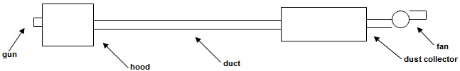
The most common contaminant in industrial manufacturing operations is solid particulate. First the contaminant is contained by putting enclosures or hoods around the dust generating machines that will allow access for the workers. The hood is then ventilated and the contaminated gas stream is cleaned by a dust collector. The dust is separated from the gas stream and the gas stream is vented to the work environment or outdoors. The process of collecting this dust, disposing of it, maintaining and servicing the dust collector equipment can expose the workers to serious hazards
a) The first hazard often present is accumulation of dust in the bottom portion of the horizontal duct runs. Most well designed vent ducts have cleanout doors every several feet. These ducts are near the ceiling usually 12 or more feet above the floor. The cleanout doors are located on the lowest underside of the duct and when the doors is opened dust will pour out towards the floor exposing the worker and environment to dust that might be inhaled. Special man hoists are recommended and breathing masks are indicated. A better approach is to install pneumatically actuated Duct Cleaner-Boosters in the system. These will momentarily increase the velocity in the ducts pushing the dust accumulation toward the dust collector. It makes the duct cleaning operation automatic and safe, with minimum exposure to the dust.
b) The next hazard is when flammable dusts are produced in the machine being vented to the dust collector. If dry dust is collected, sparks can be entrained from the hood(s), and carried into the collector. There is a coating of flammable dust on the filter elements. The velocities through the filters are much lower than in the duct and if a spark reaches the filter elements, the dust may reach the ignition temperature and start a fire. In well designed ductwork the flow is designed to be laminar. Sparks may be transported for more than a hundred feet. To guard against this occurrence, an in-line spark suppressor with a duct cleaner – booster should be installed. The suppressor device will induce extreme turbulent flow which cools the spark below the ignition temperature and protects against fires.
c) Explosions are another operating hazard. To have an explosion the concentration of dust in the housing or duct must be between the lower and upper explosive concentrations and a spark must be present. In mechanical cleaning (shaker) collectors, the flow is stopped in the filter compartment and the filter elements are agitated all at the same time. A potential for an explosion occurs since the concentration will likely pass through the explosive limits during this action. Protection consists of grounding the filter elements to prevent sparks generated during cleaning. Additional explosion rupture panels are installed and vented outdoors. In continuous cleaning pulse jet collectors, only small sections of the collector are reverse flushed. Around each bag in the cleaned section is a very small volume of air which can pass through the explosive limits. Even if a spark is present, an explosion would be dissipated without danger. If the collector filters are to be replaced the first procedure is to remove as much flammable or explosive dusts from the filters as possible. The exhaust fan’s direction is reversed to maintain a low flow and prevent dust from returning to the hood. The collector is cleaned one section at a time allowing time for the dust to settle into the collection hopper. After several complete cleaning cycles a large portion of the dust will be ejected. This lowers the exposure of the worker in handling the filter elements.
There are two general types of filter elements; those with smooth surfaces usually cylindrical or oval with smooth surfaces, and, pleated filter elements. There is a potential for pleated filter elements to bridge and have dust collected in the valleys of the pleats. Even if a reverse pulse collector is cleaned slowly with the fan reversed, considerable dust may be present in the valleys. Recent new technology provides for wider pleat spacing and stiffer filter media which allows off line cleaning as described above to be effective.
d) There are some contaminants either liquid or solids which are not suited to fabric media collectors. They will not form a filter cake or the dust is very unstable. Gunpowder and the propellant for inflating air bags in an automobile are two common examples. The most common approaches are gas washers that scrub the contaminant from the vent stream. Another approach is to mix inert dust into the vent system so the dry powder mixture is no longer flammable or explosive. Some operations will produce dust that is so wet that it will quickly turn the filter cake into a mud which will blind the filter elements.
e) Wet Dust Collectors have a variety of designs and must deal with the problem of surface tension of the water which is used to clean the gas. To get adequate collection efficiency, historically designers have resorted to higher pressure drop designs so that the solid and liquid contaminants might penetrate through the scrubbing surfaces. The same types of compounds, as in dust suppression systems, allow operating at very high efficiencies with minimal power consumption. It was necessary to design special multi-pass mist eliminators to collect the overspray from the scrubbing surfaces. Therefore gas leaving the collector is often below saturation from the heat regain as it passes through the exhaust fan.
Other Hazards and Considerations
Rotary Feeders located in the bottom of a collection hopper can pose a danger to maintenance personnel. There are instances where the feeder fails and dust builds up in the hopper. This dust can ignite and burn. The main approach is to shutdown the section of the collector and let it burn depriving it from getting oxygen. Normally, it will self extinguish. Spraying in water can create an explosion as the water displaces the dust with steam and will go through the explosive limits. On a power plant boiler, a maintenance man decided to pour water into the hopper. The dust was agitated and an explosion occurred.
A) It is preferable to install collectors where the filter elements can be changed from outside the collector housing. Collectors with removable roof doors are widely available. When a filter element extends 8 feet above the doors, even a moderate wind is a problem and workers must plan to protect themselves from these forces.
B) Another type of design is walk-in-plenums. There is a housing tall enough to change the filters, out of the weather elements. The entrance is usually a hinged access door. Rarely do these chambers have lighting. A particular hazard is when in the housing the door slams shut. It is hard to find the door in the dark and a wind can keep it closed. It is advisable to clamp the door with a cable and lock it. Remember the bags and cages must be lowered to the ground and hauled up again and fed to the collector through the access door. The pulse pipes must be removed and temporary storage space provided. These pulse pipes can fall through the holes in the filter mounting plates, forcing a man to enter the collector. Toxic gases can seep into the clean air plenum, so, the breathing zone should be monitored. When a collector is initially started, dust will seep into the plenum until a filter cake is formed. Personnel should not enter the plenum until this conditioning of the filters is completed.
For more information:
Gary Berwick, P.Eng.
Phone: (519) 746-2424
e-mail: gary@qamanage.com
www.qamanage.com