Quality Air Management

Baghouse Dust Collector

Showing posts with label explosions. Show all posts

Wednesday, April 20, 2016

Welding Laser Plasma Arc Processes Causes Major Problems

Welding laser plasma arc processes include welding fume capture, plasma and laser cutting tables, thermal spray operations. Each of these present unique and difficult issues that will cause a dust collection system to fail.

Welding

Two Stage Electrostatic Collectors; Venting welding fume operations poses some difficult application decisions. Years ago, the preferred method of collecting weld fume was with two stage electrostatic precipitator dust collectors. These had several advantages; they were relatively compact and were generally very effective on general ventilation applications. They could handle relatively large gas volumes through the collectors and generally were located near the roofs of buildings.

Efficiencies of general ventilation; The collection efficiency was variable depending on the velocity going through the collection plates. The lower the velocity through the collectors the higher was the collection efficiency. The same collector might have an 80% collection efficiency at 6,000 CFM and a 98.5 % efficiency at 1,000 CFM The same collector could be applied to different exhaust volumes that would vary as much as a ratio of 6:1. The higher the volume would produce the lowest efficiencies. But the same air would be re-circulated and an acceptable level could be maintained in a particular room or building. The cleaning of the precipitators were accomplished by a detergent wash system.
Loading for general ventilation; The loading for general ventilation units were from 0.1 to 0.5 grain per thousand cubic feet of volume. The washing frequency was typically once or twice a week. The presence of condensed hydrocarbons along with the fume was not a problem. Generally these would be oxidized into solids by the time the filter was washed. These collectors were generally the same ones that were applied as air filters in HVAC systems. The washing systems were designed for 1000 cycle life. This would translate to over ten years of life under these low loading conditions.

Hooded Systems; The trend was to hood the welding operations. The venting of hoods had some pronounced effects on the application of these precipitators. The load would vary from 5 to 20 grains per1000 CFM.

Effects of hooded systems; Usually the washing requirements were to wash the filter every shift or twice per shift because the load was so much higher. On a two shift operation, and washing twice per shift, the washing system had a life expectancy of less than 52 weeks.

Plating; It was necessary to operate particular precipitators at lower volumes with their associated higher efficiency, because of a phenomenon called “plating”. Referring to figure 1, the precipitator will ionize the gas and the welding laser plasma arc particles. As the dust passes through the precipitator it forms a bubble type shape, containing charged particles, which were not collected on the collection plates. The gas quickly loses it’s charge. However the dust that was not collected keeps it’s charge a little while longer and loses its charge as it leaves the boundary of thebubble marked “A” in figure 1. If the precipitator has a low efficiency the bubble is much bigger as marked by “B”. This low efficiency bubble is 2 to 20X as bigger in volume than the high efficiency bubble.
Under certain atmospheric ambient conditions, this low efficiency bubble starts to grow rapidly until the whole room atmosphere is ionized and the room and all the contents become collection plates for the dust. The dust s attracted to the walls, windows, machines, eyeglasses and every object that is grounded. All the surfaces turn blackened within seconds. There have been cases where this happened after the walls were painted white. After the atmospheric conditions go back to normal the plating stops.
Bad Inlet conditions. All precipitators either single or two stage need even velocity distribution across the plates. If we had a gas stream averaging 100 fpm that would be designed to operate at 95% collection efficiency and the real velocities entering the plates varied from 50 to 150 fpm, the section at 50 fpm might have a collection efficiency of 98% and the section at 150 fpm would be running at 80%. This would mean that the overall efficiency might operate at close to 85%. This condition would cause phenomenon described above
Lower Efficiencies, caused by running at lower average velocities were common. In the example above the collector might be selected to run at 125 fpm and an average efficiency of 85%. Plating may be produced because of these lower velocities and lower collection efficiency. As a result, many collectors were purchased based on volume and the supplier’s guaranteed higher collection efficiencies. There were practically no way to specify the collectors except based on supplier claims. Velocity was not a good criterion. Some collectors at relatively higher velocity and longer sets of collection plates would achieve the same result as a collector with short plates and a slower velocity.
Electrical Controls; To further aggravate the problem improper electrical controls were offered. Some operators interpreted SIC controls to mean arcing was not allowed. To eliminate the arcing across the plates, they lowered the voltage controls to halt this sparking. Unfortunately the voltage was lowered so much that the particles were not charged. There were cases where the metal pre-filters were more efficient than the precipitators.
Insulator Coating; The main collection plates are at ground in a two stage electrostatic precipitators. The charged particles will be attracted to the lower voltage intermediate voltage level plates and to the grounded collection plates. The insulators were also at ground level and some of the dust (a very small percentage) stuck to the surface of the insulators. This was a very strong bond and the spray cleaning systems could not keep these insulators clean. Eventually they were coated badly enough that the power supply could not keep the charging electrodes to ionize the gas and the particles. To correct this problem required a major overhaul of the precipitator. The charging electrodes were made of very fine wires and would eventually break and require replacement. Most electrical maintenance men were not familiar with high voltage supplies and maintenance was neglected.
Innovations in Design; In the late 70’s, two stage precipitators with pressurized insulators and more rugged washing systems were introduced. The insulators were subject to a gas stream that entered the collection compartment at a higher velocity than the collection velocity across the plates. This protected the insulators from charged particles. The charging electrodes were made heavier to give much longer charging electrode life.
These innovations increased the collection costs with electrostatic collectors to the point where cartridge dust collectors introduced at the same time were more economical to purchase and operate.

The advantages of the electrostatic collectors were:

  1. The pressure drop was constant and usually low.
  2. They could collect liquid droplets.
  3. They had the potential of long periods of service without maintenance.


Cartridge Dust Collectors

With the development of cartridge collectors, another method of collecting fume dusts became available. The standard design pulse jet fabric collectors with cylindrical bags did not work because the cleaning systems propelled dust through the cake of adjoining rows of bags during the cleaning cycles. In the late 70’s and early 80’s thousands of cartridge collectors were applied to both hooded and non-hooded ventilation systems.
Problems developed in many systems after the mid eighties. High-pressure drops and short cartridge life developed in many systems. The causes were one or more of the following:
The presence of thin films of oil on the surface of the parts that were welded. When electrostatic powder coating finishing systems were widely applied to reduce or eliminate hydrocarbon generation from paint systems, the faces of steel parts required protection from oxides on the surfaces. During the welding process condensing hydrocarbons were liberated and swept up into the ventilating systems and their associated collectors. One of several results followed:
a) The solids to liquid ratio was so high that the dust blotted the liquids and the collection system was not affected by the liquid droplets.
b) The solids to liquids ratio was in range where the powders and hydrocarbon mixture formed a paint and the collection media was gradually plugged. This could take days, weeks or months, but the net effect was the cartridges had to be replaced or laundered pre-maturely.
c) The solids to liquid ratio was so low that liquid wetted the cartridges and they were plugged as in (b) above. Even in cases where the coating was barely discernible, this could occur.

A case in point was in a plant making stainless steel mufflers. The metal was washed after forming and the load in solids was 0.02 grains per 1000 CFM, the pressure drop rose in a six month time period. The re-enforced cellulose media would be air-dried and the pressure drop would be reduced from six inches to 0.3 inches after the elements were installed. After 4 months the pressure drop went up to six inches. After washing the pressure drop went down to 0.8 inches. The next washing cycle came two months later and the pressure drop returned to 1.2 inches. It was less expensive to replace the cartridges than to wash them in such a short interval.

Washing cellulose media cartridge elements: After each washing, the media is wetted, the permeability of the media diminishes, even if no dust remains at or below the surface of the media. The wetting causes the media to matt. If oil wets the media it is a good blotter and the fibers may grow. This causes the pressure drop and base permeability to decrease.
Other media are available that can be washed and are not wetted by oils. These are referred to as oleophobic media. This is a coating on the fibers that does not change the permeability. Otherwise they will be called washable. Often they can collect a mixture of fumes and hydrocarbons because the fibers do not swell.
Treated Spun bond medias are widely applied. Some of these are excellent choices but have limitations. For instance, with tight pleats, the top of the pleat may squeeze so the media in that portion of the pleat may make contact on the clean side when the pressure drop rises. On some applications, over 80% of the pleat of the media may not be effective. The remedy is one of the following.
A) Provide pleats with wider spacing and make them shorter in depth. This will allow full use of the media available in the filter element.
B) Provide a media that has stiffness and will not collapse on itself.
C) Provide a laminated media with the clean side backing very open so that if the pleat squeezes there will be flow through the media.

De-agglomerating dust; Normally we would run a properly designed dust collector at 1 to 1.5 inch water column pressure drop. Sometimes a system will only stabilize at a higher reading (E.G. 3 to 4 inches). One possibility is that it takes 3 to 4 inches to cause the dust to agglomerate and fall to the hopper. It may be de-agglomerating when you pulse at lower pressure drops. In that case off-line cleaning should drop out the de-agglomerating dusts. Some dusts are more susceptible to this phenomenon than others. Often, they put an anti-rust wipe on the material being cut. If it contains ceramics then we will have this problem.


Fume Generating Processes Similar to Arc Welding and Gas cutting


Thermal Deposition Processes

Spray Coating The first type was a flame spray coating machine. These fed a material into a high heat gas torch. The temperature achieved was so high that feed material would produce a material in gaseous/liquid form that started to condense into molten droplets. Though the process is not understood, it is presumed that some of the adhesion was from a nuclear bonding, in addition to the cooling of the molten droplets on the piece to be coated. There were some materials that were too porous and there was limits to the thickness of the coating. The over-spray that did not adhere varied from about 5 - 20% of the material fed into the coating generating gun. The over spray was generally collected by medium pressure air washer scrubbers at a 99% collection efficiency.
Plasma Arc Spray To get smoother surfaces and better adhesion to the target surfaces, an electric arc was added to gas flame. This produced much higher temperatures in the gun at the point where the powder or wire feed entered. It generally produced more over spray (10%-40%). This over spray was much finer and would lose its ability to stick and adhere to surfaces. This over spray was too fine to be collected efficiently with air washer wet scrubbers. Fabric or pleated cartridge collectors were necessary.
One serious problem was encountered. This involved residence time of the dust between the gun and the media collection surfaces. In a system installed in 1975, on a plasma arc spraying machine for coating electrical capacitors. The process was coating plastic surfaces with metal. The cartridge collector filter elements, venting the over spray, plugged up in less than ten minutes. The six cartridges each with 50 square feet of filter, (300 sq. ft. total) received less than 250 grains of dust. The dust collector was connected within 20 inches of the gun. The over spray dust adhered to the media surface and blocked the pores.
Through experimentation and field experience it was determined that if the dust stayed in the gas stream for relatively long periods of time, it would lose its ability to coat the media. Depending on various factors such as the feed rates of gas, solids and the arc current, this time varied. It varied from 0.5 to 1.0 seconds. Referring to the next figure, the residence time will be analyzed.

The part to be coated is placed in a hood with the gun at the front of the hood. The hood is 6 foot long and is rectangular with a 4 x 4 opening. The face velocity of the hood is 350 feet per minute. The duct is sized at a 2500 feet per minute duct velocity and the duct is 15 feet long. We will assume the back of the hood has a transition 2 foot long, designed like an evasé to have uniform velocity distribution.
1) Time to travel through the hood 6 ft / 350 FPM = 0.017 seconds
2) Time to traverse duct to the collector 15 ft / 2500 FPM = 0.006 seconds
Residence time = 0.017 + 0.006 = 0.023 seconds.
The flow through the system is 350FPM x 16 sq. ft. = 5600 CFM

To re-design collection for longer residence time the length of travel in components are altered and the velocity can be modified. The hood is the first to be looked at.
3) The hood would be made 10 foot wide with the same 4 foot by 4 foot opening for the gun and part. The velocity in the wide part of the hood would be 5600 CFM / 100 sq ft = 56 FPM
The residence time in this portion of the hood would be 18 feet divided by 56 FPM = 0.32 seconds.
4) The duct could be extended to 200 ft by putting in ductwork in a “serpentine fashion” and enlarged to drop duct velocity to 1,000 FPM. The residence time in duct would be 200 feet/ 1000 FPM = .0.20 seconds

The residence time of the system would be 0.32 + 0.20 = 0.52 seconds.

High Temperature Cutting Processes


This high temperature flame coming from the gas gun proved to be an excellent improvement in flame cutting. Instead of jagged edges near the cut, it became much smoother and for most applications it did not require smoothing the edge or the operation was very quick. With digital cutting machines the precision rivaled other cutting processes.

Plasma cutting and laser-enhanced cutting are in common use. The type of dust produced runs the gamut from arc welding to that of metalizing operations. Most dust is more similar to venting systems for arc welding operations, but to get some cutting characteristics the temperature and flow in the gun are adjusted. This may produce a dust that is prone to coat surfaces and media. When this happens the residence time requirements may be in the same range as the electro deposition processes. Laser cutters work well with 1 second residence time. Some flame cutters have been applied to non-metallic pieces such as wood and plastics. These dusts can contain tars, and oils from non-metallic parts and the collector media can get plugged easily, within a few seconds. With metallic parts, the oils can be an imperceptible film on the metal or originate from the compressed air compressor. In that case, a low-pressure scrubber may be a good choice. Roll filters with replaceable media or a self-feeding pre-coat material system have been employed.
It is crucial to have the correct airflow at initial start-up. Too much airflow will reduce residence time and cause the painting effect. Install a control damper in the main duct and use an approved method to accurately measure the exact airflow. Use the damper to choke the system if needed.
Recently, it has come to our attention that some plasma cutting processes are throwing out the 1 second residence time rule of thumb. Either the process temperature is being cranked up so high that the molten metal atoms still don’t have enough time to form molecules or the dust concentrations are so low that the atoms never get a chance to collide with one another in the laminar flow of the duct system. In these cases, finding the correct residence time
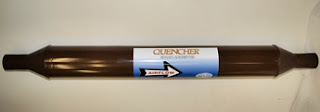
is almost a trial and error process. A new product has come on the market, called a Quencher, which is inserted in the ductwork as close to the source of dust as possible and no less than 10 duct diameters upstream from the collector. This device imparts a high energy multi-directional swirl to the air stream which cools the metallic atoms, accelerate their oxidization, and forces them to collide together and form molecules which can safely be collected without the painting effect.

Use the links below to obtain more information on welding laser plasma arc applications.


Monday, October 19, 2015

Spark Arresters and Coolers

Important Factors in Spark Arrester Selection
(1) Pressure drop across QUENCHER style of unit is a function of the Reynolds number which is proportional to the density for air. This means that a unit can be sized smaller if operating at a higher temperature. For instance a suppressor operating at 440 degrees F is 2/3 the size of the typical unit applied at 70 degrees F and the pressure drop will be designed the same. This lowers the cost of the suppressor. The density is also affected by the water vapor in the gas stream. It has little effect at temperatures below 125 degrees F but can be a major factor when operating at higher temperatures.
(2) If the gas steam has dust that might drop out in the duct at the velocities in the blender style or QUENCHER suppressor, a booster must be provided to periodically remove this accumulation. If this unit is not kept clean it might pose a threat by putting an extra load on the duct-work. Without an Automatic Booster System, the suppressor might require periodic manual cleaning.
(3) The booster design is also temperature sensitive and must be altered to accommodate changing gas steam conditions. Most suppliers do not have the capability to modify these booster designs.

There are several approaches to the issue of extinguishing sparks in a gas stream.

Cyclone Dust Collectors
Contrary to common belief Cyclones are not an effective spark arrestor. For a spark arrestor/cooler to work, there must be turbulence to be effective. If you have turbulence in a cyclone pressure drop is very high. They are designed to avoid turbulence. Many bag house fires occur in systems with cyclone pre-cleaners. Amazingly the inlet baffles on the bag-house are more effective as spark arrestors, however they are not foolproof.

Static Baffle-Box Spark Arrestor
Many dust collector suppliers offer this type. It consists of air entering at one end of a baffle box running over a baffle plate which drops out the sparks and much of the dust collected. The air exits at the other end, and then travels to the dust collector. The big drawback is that a hopper and flexible or solid hose connection to a collection barrel is required. Also, these devices do not eliminate all of the sparks. There is not enough turbulence generated to ensure hundred percent spark arrestance. Sparks may ignite the contents of the collection bin

Mesh Filters
This is a common stop-gap measure where the filter is placed at the exhaust duct of hoods or installed in the duct-work. When clean, the mesh filter will stop at best 80% of sparks. These filters do not produce enough pressure drop to be fully effective. It only takes one spark to ignite dust in the duct or set a dust collector on fire. The only thing these filters do is clog up and add to your maintenance.

Blender Type Air Mixers
A number of these air blender/mixers have been applied successfully as spark coolers and suppressors. Over the last 5-6 years standard air mixers have been adapted and applied between the spark generating process and dust collector. They were applied in processes where fires in the dust collectors had previously occurred. One supplier hired a consultant to develop a market for these air blender/mixers as a spark arrestor/cooler. This blender design was an outgrowth of mixing two gas streams of different temperatures to insure a uniform temperature after the static mixer. It was deduced that the gas stream produced turbulent flow as it passed through the blades and this was the reason it could be adapted to spark cooling. However, these are air mixers first and spark arrestors second. There are performance limitations because not enough turbulence is imparted to the spark ember.

Improved Spark Arrestors
QAM developed the QUENCHER, which is a variation of the blender/mixer design. Employing a 60 year old spin vane mist eliminator technology developed by Sly Manufacturing in the early 1960’s, led QAM to vary the blade designs to have the most effective performance, inducing maximum turbulence to the gas stream, and lowering the cost. Maximum turbulence is the key to spark arrestance. After several tests it was found that the air blender/mixer design did not impart enough turbulence and some sparks got through, especially at low gas stream velocities. Eventually, there was a specific design which imparted the most effective swirling and turbulence thereby extinguishing the sparks quickly and most effectively. In fact, during testing of the QUENCHER, the arrestor cell would light up as a ball of fire, however, one inch past the cell nothing was left in the gas stream. These designs were incorporated into the QUENCHER. QAM has developed special application data in which the blade angles are adjusted to produce minimum pressure drop for different temperatures and gas densities. To our knowledge, no one else accounts for the gas density effects on spark arrestors. In truth, due to the advanced design, even applying the incorrect parameters to a QUENCHER may not result in a failure to put out sparks. Since the pressure drop across the blender and mixer are a function of the velocity through the device, the development of a pneumatically operated booster was introduced to prevent dust dropout accumulating in the static blender/mixer. It also blows out accumulations on the blades.
Read more: Quencher Spark Arrestor


Liquid Spray Systems.
For many years these systems were the only available systems to prevent fires caused by sparks. The system consists of electronic detectors that detect sparks and react to their presence. When a spark is detected liquid sprays are actuated and water sprayed into the duct. The sprays actually cool the gas stream below the dew point. However, in dust collection systems, the water then wets the filter bags or cartridges. This prevents fires but the gas flow is interrupted and the bags must be either replaced or dried out before the process can resume. The detector sensitivity can be lowered to prevent excessive actuations, but, this reduces the reliability of the systems. The detector missing a spark is an ever present danger and a fire may occur. Bag or cartridge replacement is definitely required.

Static Blade Spark Suppressor (Tri Pass)
These were developed in Japan to replace multiple cyclones in Coal fired boilers. They found that the multiple cyclones did not stop sparks from entering the dust collectors. The first ones were installed in the early 70’s. They ran at 1.5 inches of pressure drop and were fabricated from structure angles to resist the wear of the abrasive ashes in the coal that they fired. There are several of these applications installed in the USA designed by one of our colleagues.

We trust that the above information will enable you to evaluate and select the most suitable method and supplier for your application. Buying our QUENCHER/BOOSTER combination will give you a risk free unit, fine tuned for each application. 

More on... Dust Collection and Spark Arrestors

Thursday, June 11, 2015

Furnace and Dust Collector Fire Hazards

Fires in brass furnaces have always been a danger.

First let us review the process; as the material is fed into the furnace it has many metals including zinc, tin etc. Some of these actually go to vapor and then condense and turn into solids.

The key is that these metals are very fine with very large area to weight ratios. The exhaust is generally cooled by mixing with ambient air so the metals are not appreciably oxidized. The dusts collect, with the other dusts, in the dust filter cake.

When the collector is shut down the metals start to oxidize and the effect is like catalytic combustion. The oxidation produces heat. The dust is usually a good heat insulator and "hot spots" occur. Sometimes the temperature is high enough to start a fire when the flow was stopped. More often, when the collector is turned on, the initial flow fans the sparks and when conditions are optimum for combustion, a fire will start. Most of the time small holes or scorching can be noticed on the bags before a fire.

Sparks may occur as scrap is added to the molten metal. This is common when the scrap is oily.  The usual time to add scrap into the furnace is at the end of the shift when the collector is especially vulnerable to fires.

The approach to prevent fires is to extinguish sparks if they are present and to cool the hot spots when air is not flowing through the system.

To extinguish sparks the flow before the collector must be changed from laminar to turbulent flow. This is accomplished by installing a QUENCHER spark arrestor in the air conduit to the dust collector.

To keep the "hot spots" cool, my suggestion is to pulse the collector off line every thirty minutes or so for one complete cycle to cool the "hot spots". If the off-line cleaning is too frequent, the cake will be destroyed or damaged, so, the cleaning must be controlled.

When selecting a fabric pulse jet collector, high-ratio technology designs can operate at filter ratios of 16:1.  Cartridge collectors are not a good selection as the pleats may promote formation of the hotspots described above.

We first used this technique at St Joe Mineral, which was near Pittsburgh, 30 years ago, on their zinc oxide furnaces. We were informed that they were venting through an AAF pulse jet collectors. AAF has managed to put out some of the worst pulse jet collector designs in the Industry. From the description it sounds like a AAF FabriPulse. That collector if it is top access design has these venturies that wedge in the top of the bag. Using the American vernacular, it sucks. The purpose of the venturi is to seal the top of the bag with the cleaning jet. There are openings around the top of the bag below the wide part of the venturi. This, in effect, allows the jet to grow until the growth is stopped by the walls of the bag. That is an over simplification of the process, but it is a fact that it sucks. The net result is that the collector cleans poorly and there is a lot of dust that is forced into the surface and subsurface filter cake.

On any kind of brass furnace it is best to keep the dust cake porous and thin. As I explained previously, in a brass and other process, the zinc goes from vapor to liquid to solid and forms zinc fume. This zinc fume because of its large surface area to weight ratio can burn or explode quite easily.

We were involved in a legal action where the customer hired a man to change bags on a MikroPul collector venting a zinc dipping operation where they were coating pipes. The young man, after he was half finished (inside removal) sat on the temporary grate and decided to light up a cigarette. The collector exploded and then burned down. He was blown out the access door with the explosion and the sprinkler heads went on after the fire started and water poured over him as he was lying on the ground.

Since we were told that the fires started when the process flow continued we need to look at the source of ignition. If the ignition is caused by sparks, the best way to suppress sparks is by going from laminar to turbulent flow in the dust before reaching the collector, with a good in-line spark arrestor. The next source of ignition might be through the cleaning jet. The cleaning jet can supply oxygen from the compressed air and when it reaches the cake maybe sufficient to cause some sparks similar to small explosions to occur in the cake. This may ignite the rest of the fine fume fuel to start a fire. This would be very pronounced, if the collector was running at a high pressure drop with a dense thick cake and frequent pulsing.

We can attack the symptoms or the causes. One way to attack the symptoms is to limit the thickness of the cake. This can be accomplished by installing PTFE membrane laminated bags. Another way to attack the symptoms is to clean the collector with compressed nitrogen instead of compressed air.

One cause may be because of the atrocious design of the cleaning system. The way to remedy the poor design is to modify the cleaning system design. To implement the change we need to throw away the venturies and modify the pulse pipes so they can run without venturies. We can get the pulse pipes modified so they will induce more cleaning air per unit of compressed air, possibly lowering the formation of sparks on the bag surface. It would allow the collector to run at a lower pressure drop with less frequent pulsing.


I always like to look at how the operation of the collector interacts in the process of venting the furnace. 

Read More...  About assistance with dust collection applications.

Thursday, October 30, 2014

Fires - Smelting Process


First we must be careful to find out if the fires are a result of ignitions by a spark. All these acids mixed with carbon can spontaneously ignite, especially if the precious metals include catalysts, such as vanadium, like they use in catalytic converters. Or, they get fires when they are in the ten hour mode? My calculations indicate that during the ten hour precious metal mode they are basically diluting the exhaust to meet discharge requirements into the atmosphere.  To discharge from the hood at 125 degrees they either need a lot of dilution air or water vapor. For 30 hours a week, they use it as a trash burner. Here again they seem to be trying to hide the true nature of the operation. In the trash burning 30 hours they probably have wild swings in emissions which might ignite poorly combusted components and would be ignited by sparks in the baghouse. I would hate to live downwind during either operation. You need to find out the following.

  1.  Do the fires occur while operating?
  2. Do fires occur when they are shut down?
  3. What are the temperatures in the ducts over a 60 hour period?
  4. If they run 8 hours a day do they run 2 hours on smelting mode and six hours trash mode?
  5. Do they insulate the duct?
  6. What is the charge to the smelter? Coins? scrap gold, scrap silver? perhaps catalytic converters?.
  7. It seems like they would have a severe corrosion problem and preheating of ducts should be considered.

We can put out sparks with Quenchertm spark arrester but we cannot remedy poor control.

The ten hour mode is the ten hours per week when they are smelting. The 30 hour mode is when they are trash burning. Get a piece of bag to examine. It will be obvious if it has been chemically attacked. You should be able to tear or burst a piece with pliers and a vise. 

For more on spark arresters, see  QUENCHER spark arrestor

Friday, October 3, 2014

Wood Fired Boilers

There are many conditions that lead to fires in wood fired boilers. The engineering solution requires recognizing the factors that contribute or cause these problems. Most are related to the combustion process and that the wood composition varies widely:

  1. The emissions from the boiler consist of dust and gases that are not completely burned. These can be ignited by sparks coming from the boiler. The loading of these pollutants can vary widely. Gases may continue burning with a flame, and, sparks may be in the process gas stream. 
  2. If we install a spark arrestor, such as a QUENCHER, before the dust collector, it will cause the gas pollutants to burn producing heat, carbon dioxide and some small fraction of water vapor. The QUENCHER will also prevent any sparks from entering the dust collector as the hot ciders will be immediately cooled to the gas temperature, as the air goes from laminar flow to turbulent flow and back to laminar flow. We now have cooled dust and ash entering the dust collector. The pulsing action of the cleaning system will fan any red-hot cinders if they are present. For reasons beyond the scope of this report, the dust cake will be dense and subject to ignition. Fortunately, conditions must be in a narrow LEL/UEL range to start a fire. With conventional pulse cleaning systems only a fraction of the filter cake on the bags is functional and the rest of the bags are plugged. 
  3. We would modify the cleaning system with modifications that would enable the full surface of the filter media to be active. This would mean that the inventory of flammable dust would be reduced by over 95% so there would be no combustible dust between cleaning pulses. Surprisingly, the cleaning frequency would also be reduced. To accomplish this, we would need information regarding the design of the existing dust collector.

When completed this would be the best design, and, barring unforeseen circumstances such as power failures at inopportune times, the system should perform flawlessly for years. The only risk is that the filter bags could be attacked chemically. 

More information on... retrofitting existing dust collectors 

Tuesday, October 1, 2013

MINI-QUENCHER Spark Arrestor for Small Vacuum lines


QAM is pleased to announce the MINI-QUENCHER spark arrestor for use in 1", 2", 3" and 4" dust collection vacuum lines. This is the latest extension of of our incredible QUENCHER in-line spark arrester line.

The Q-1, Q-2, Q-3 and Q-4 spark arrestors answer a demand for spark protection in these smaller applications. Until now nothing has been available on the market for vacuum dust collection applications.
Spark arrestor

The MINI-QUENCHER:

  • needed for welding, grinding, cutting operations
  • extinguishes and cools sparks and embers that set fire to dust collectors and duct work
  • in-line device, that is easily inserted in the duct work or vacuum tubing
  • no maintenance, no additional drop out collection point required
  • no moving parts, static device, no power required
Quencher spark arrestorMini-Quencher spark arrestor

More on... The Mini-Quencher

Monday, August 20, 2012

Spark Arrestors and Booster - Duct Cleaners

Service Reports:

Chambly, QC: The installation was at a microbrewery. This is a problem common to all breweries that recycle their boxes. In the process, they have an automated machine including a band saw which cuts up the boxes and then bundles the cardboard for recycling. A good deal of paper dust is generated by the process and needs to be collected through an extraction duct from the saw to a dust collector.
The problem is that these boxes may still have staples and bottle caps in them. When the saw hits the staple or bottle cap a spark is generated which is drawn into the extraction system and produces a fire in the duct and in the dust collector itself by igniting the cardboard dust.
Our proposal was to install an LC series high ratio dust collector providing the maximum filtration efficiency and making the system the most compact possible. Floor space was an issue. However, to protect both the duct system and dust collector from ignition, a QUENCHER in-line spark arrestor/cooler was installed in the ductwork at the outlet of the extraction hood for the band saw.

Read more about ... Quencher Spark Arrestor

The installation has been running since June 2005. The maintenance supervisor indicated that the system should have caught fire within a maximum of two months of operation, which was the experience they've had until then on the other systems in the plant. There have been no incidents to date. He also stated that there was no light dust accumulation around the dust collector outlet which was typical in the other systems that they had. This is an indication that the dust collector is operating at a high level of efficiency and that there has been no sparks which would have burned holes in the filter material.

London, ON: This is a metalworking shop which does a good deal of welding and grinding. The dust and fumes are extracted to a central dust collector through source capture articulated arms and downdraft tables. These processes produce a lot of sparks which get drawn into the dust collection system.
In one system, the main duct line is oversized and the dust is dropping out into the duct work prior to reaching the dust collector. As a result, the sparks that are transported through the duct will ignite this volatile dust in the duct causing a fire to be drawn into the dust collector.
We recommended that they. install a "booster duct cleaner" which would blow this settled dust down the duct and to the dust collector before it could be ignited by the sparks We also recommended that they install a QUENCHER in-line spark arrestor/cooler to quench the sparks and prevent them from going down the duct work. The client has yet to install the booster which means that he has not solved the dust settling problem but they did install the QUENCHER. Since the installation of the QUENCHER, there has been no further ignition of the dust in the ductwork or in the dust collector.

Read more about ... Booster-Duct Cleaner

Monday, October 24, 2011

Quencher (spark arrestor) with Plasma/Laser Cutting

Some people have used Quenchers, and other style spark arrestors in plasma and laser cutting applications but still experienced fires in their dust collectors. In the majority of cases, the Quencher alone is sufficient to control dust collector fires. However, in some isolated cases, sparks are only one issue to deal with these applications. A good spark arrestor is definitely needed to stop sparks and embers, but, it is no guarantee against fires in the dust collector.

The problem:
1.    The operator may have to reset the heat setting of the plasma head. It could be generating too much atomic static particles. This causes a "painting" effect on the cartridge media, eventually clogging it.
2.    Large heavy particles of molten metal can be generated in the process.
3.    You should use spun bond wide pleat cartridges, to ensure proper clean out of the cartridges. That way the dust will spread over a large surface of media, instead of on the outer surface only.
4.    Current cartridges that are clogging over time (can vary from hours to weeks, depending on loading). When clogging occurs, the air flow drops and sparks can slip through any spark arrestor (not just the Quencher). This sets fire to the combustible dust accumulated on the surface of the cartridges.

Normally, plasma cutters have different characteristics depending on the settings of the cutter torch. The quantity of dust produced is relatively small. At some torch settings the dust is reactive by initiating an atomic bond between the dust and the surface of the cartridge, forming a hard durable impervious coating which totally or partially plugs the filter media. This mechanism is an inherent part of the plasma coating process to put wear resistant coatings on shafts, turbine blades etc. that allow the parts to receive very long lives. In the plasma coating machinery, the key to collecting the overspray in cartridge or fabric collectors is to allow the atomic bond to dissipate. This is accomplished by extending the time that particles travel from the torch to the filter media elements. In plasma coating systems at this time, depending on torch settings will vary from 0.5 to 0.8 seconds depending on the metals being sprayed.

In plasma cutting applications often the dust being emitted from the torch does not require any special considerations. In fact, collectors can operate for many months quite well with moderate pressure drops. Then the torch settings are changed because of various factors such as the composition or thickness of the pieces that are cut. As the settings of the gun or the speed of the cut is changed, the dust can act as a plasma coating torch and the cartridges start plugging. Sparks are often produced. If the dust is combustible the sparks may ignite the coating on the cartridges. Normally the fuel on the cartridge surface is not very heavy so the fires do not damage the housing of the collector. The cartridges are then usually replaced. The QUENCHER spark arresters are sometimes applied to limit the risk of fires and extend cartridge life. In the tandem horizontal type collectors, the cartridges are usually tight spaced, so, as the pressure drop rises, the pleats are pinched in the valleys so the pressure drop goes up. Combustible dusts can put pounds of dust to be stored in the cartridges to fuel a fire in the collectors. However, the squeezing of the pleats also causes pressure drop to increase and slow the flow through the dust collector. This often allows dust to be released into the work area.

Although spark arrestors will protect the system from sparks, pieces of molten metal go through the spark arrestor unaffected. These heavy, hot particles lodge on the surface of the cartridge and ignite the combustible dust coating. The heavy molten particles need to be dropped out of the system prior to the spark arrestor and collected safely, so as not to cause a fire in that collection device. Cyclones and drop out boxes are sometimes used for this. However, be aware that these devices have little effect on sparks / embers which are light buoyant particles and slip through to the dust collector.

An excellent example of these effects was the experience of the Day division of Donaldson who supplies this design. In cutting the filter mounting plates for their design they plasma cut holes in a 1/4 inch thick plate. They found that the filters plugged quickly in the after filters. They added distance in the filters venting the operations. This experience occurred 20 years ago and we do not know how this operation is now performing.

Our recommendation is to replace the current cartridges with a wide spaced stiffened spun bond media carried and pre-coat the cartridges with a 1/64 inch thick coating of inert pre-coat material.

We suggest you send each job application data (layouts & pictures) to QAM technical support at gary@qamanage.com and/or call 800-267-5585. We’ve dealt with plasma cutting applications for decades and feel that yours would be a common problem. If you contact us, we'll be happy to work with you on this.

More about... Spark Arrestor applications with plasma/laser cutters (PDF)

Wednesday, August 24, 2011

Coal Dust and Quenchers

First let us review the facts on explosions.

Explosive dusts have lower and upper explosive concentrations. An explosion can only occur if the following is true. Assuming we have outside air with 20% oxygen being used to ventilate the mill, it is probable that the outlet from the hammer-mill will be between the upper and lower explosive limit concentrations. Between these limits if there is enough energy in the spark that ignites the dust, an explosive flame front will be triggered and move along the duct toward the ventilation outlet and presumably toward a dust collector, and, we are assuming this is to be a fabric (baghouse) collector. Determining the upper concentration limit is very difficult. The lower explosion limit is around 30 grains per SCFM for combustible dusts like coal. Once an explosive flame front is ignited the normal procedure is to put explosion vents in the ducts and collectors.

The action of Quencher spark arrestor.

Our Quencher spark suppressor works by changing the flow in the duct to turbulent flow. During laminar flow the spark can be carried for extremely long distance as the spark travels with a layer of air which insulates it. When turbulent flow is induced, the spark is immediately cooled so it lacks sufficient energy to start a fire or trigger an explosive front. Most insurance underwriters require explosion venting of the duct systems and dust collectors. The way of achieving this conversion from laminar to turbulent flow is by slowing the air down to lower the power consumption of the conversion device. The conversion device thoroughly mixes the dust laden gas stream with propeller type fixed vanes to extinguish the spark(s). To rid the potential low velocity build up of coal dust in the spark arrestor, it is periodically boosted in air stream speed to sweep the dust into the collector. This uses a compressed air propelled stream identical in design to that of a reverse pulse jet collector with time durations similar to that in those dust collectors. This the “Booster - Duct Cleaner” option is offered with the Quencher spark arrester.

Read more about ... Quencher Spark Arrestor

Thursday, July 7, 2011

QUENCHER Application to Various Processes

This is an overview of the potential for the QUENCHER spark arrestor in the ventilation market. It may seem detailed but the terms had to be defined as well as recent approaches. This can be exciting for all of us.

FOREWORD
Many gas steam processes, especially in powder collection systems, are candidates for the application of low cost gas mixing products as the Quencher supplied by Quality Air Management.
Note that embers & sparks get extinguished in the Quencher cell itself. Combusting material, such as paper or wood shavings, must be completely consumed within 4 duct diameters past the Quencher (where there is still enough turbulence) and taken the form of embers to be extinguished.

1) SPARK COOLING
Prevention of Sparks entering Solids separator (dust collector) equipment and starting fires
Definition:  First we must define a spark. A spark is a piece of solid particulate which is completely oxidized and is at a temperature of 600 degrees F or over and which is above the ignition temperature of the powder being collected or above the ignition temperature of the filter elements.
Effects of sparks: Sparks can be carried along in the exhaust gas stream in laminar flow and will not cool off since cooling requires a difference in velocity between the gas and the spark being transported. Therefore, the spark will be carried into the solids separator and deposited on the filter element surface where it has a possibility of igniting the surface. If ignition occurs, the fire may spread and cause damage and produce harmful gases.
Response by the QUENCHER to sparks occurring in exhaust stream: The static blender converts the laminar flow to turbulent flow by thoroughly mixing the solid sparks with the gas stream, reducing the temperature of the sparks below the ignition temperatures of the filter media and the powder transported through the system.

2) HIGH TEMPERATURE COATING AND CUTTING PROCESSES
Originally a lot of these operations were performed by cutting with an acetylene torch to cut metal and with flame spray equipment which fed a wire into the flame of a gas torch to produce coating on various metallic and non-metallic surfaces.
The torch cuts were very coarse and had to be ground or put into other cold forming devices to make the parts usable. Often these cutting torches were applied to cutting up and reclaiming scrap. Most venting systems for torch cutting were vented into general ventilation and HVAC systems.
The flame spray equipment was limited to certain thicknesses and uniformity was such that on many parts subsequent grinding and smoothing operations were necessary. The coating produced was relatively coarse and the overspray was easily collected by low pressure drop wet powder collection devices. This avoided any requirements for mixing equipment.
The Advent of high temperature technologies was developed in the 1980-90’s decade; Lasers, plasma, and arc tools have been applied to the processes long dominated by gas torches and sprays. These new technology systems are much more intense, quicker, more accurate and more efficient than the old gas flame units. The temperatures developed in the devices are sufficient to vaporize metals and actually increase the temperature above this value. These systems can take sharp cuts and make intricate cuts, cut fine round holes replacing shears, drill with little or no need for grinding or finishing. They can process thick plate or light gauge sheet metal with the same machinery. They are guided by CNC controls for maximum flexibility. Applying these processes to spray systems is also very effective. The spray process must be explained prior to treating the ventilation of the high temperature cutting devices. These are the fastest growing fabrication processes in the world.
Spray systems; These systems were vented into relatively large gas and powder over spray collection hoods. They produced particles with a very strong attraction to the parts being coated. Some have theorized that the bonding is at the molecular level. When it strikes the surface to be coated it bonds to the surface as if the coating was integral with the object that is in the path of the spraying device. The coating is either fed into the device as a powder or a wire.  The particulate overspray is relatively light in dust loading and the hood is vented to a dust powder collector. The wet collectors are not sufficiently effective to collect this much finer overspray. To develop sufficient collection efficiency, the overspray is vented to fabric or cartridge collecting device. The overspray is still attracted to any solid it gets near and will form a hard impermeable coating which can seal the surfaces of filter collection elements. These overspray particles though much finer than the sparks described above are carried along in ducts which have laminar flow. They must lose their attractive ability before they reach the dust collector / powder separator. If the powder spray is given sufficient time in flowing through the duct work, it will lose its coating ability. Typically the residence time of the dust flowing in the duct, is designed for about one second and sometimes up to 1.5 seconds. For a system running at 2400 feet per minute at least forty feet of duct work would be required between the hood and the collector. Most plants do not have the room for these long ducts. We theorize that a QUENCHER element could allow the reduction of this residence time by as much as 90% and be more predictable than the residence time especially as newer spray compounds are being developed.
Venting High Temperature Cutting Systems; Although the dust venting from the cutting processes do not have as high an attraction as the coating guns, the dust has the same problem. Residence times are often in the 0.5 to 0.7 seconds. Because the dust loadings are so low and the customer often removes the coated filter elements and vents outside, the emissions will be lower than most air pollution codes. However, if the dust could be collected and neutralized, the savings in heating and cooling costs could pay for a QUENCHER device in a month or so.

3) GAS MIXING IN POWDER SEPARATORS
QUENCHER gas mixing cooling of gas  streams; Usually all gas streams are designed for the lowest pressure drop to save on power consumption in moving the gas from one point to another. This is accomplished by moving the gas in a flow pattern called “laminar flow”. In effect the gas stream is divided into cylinders that flow parallel in the duct work so that little or no mixing occurs between these cylinders within the walls of the ductwork. The other flow in a duct occurs when “turbulent flow” occurs. This is a violent mixing that occurs and will quadruple the pressure drop if it occurs in a length of duct. The gas follows the path of least resistance and naturally wants to revert to “laminar flow” when the disturbance or duct element, which produces the turbulent flow is removed. Both laminar and turbulent flow pressure drops are a function of the average velocity through the ducts. If we mix two gas streams flowing through well designed transitions that maintain laminar flow in the total stream, the resultant is that the gas streams will continue in the duct with little or no mixing of the combined gas streams. For instance if a gas stream at 300 degrees F is mixed with one at 100 degrees F, the resultant gas stream will be stratified and continue through the system with part of the flow at 100 degrees and part at 300 degrees. There might be a very narrow layer of the flow that mixes.
The proprietary QUENCHER design is such that the whole cross section of the duct produces an effective mixing with a minimum penalty of pressure drop by producing turbulent flow through the mixing element. 
Temperature Lowering Processes for Solids Separation; Some powder collection gas streams use various means to cool the powder laden gas streams by mixing ambient outside air to reduce the gas temperature (and associated powder temperatures) to a level where a fabric media powder collector can separate the powder and gas for subsequent collection of the solids. A typical operation of this type is on a clinker cooler system in a cement plant. The gas temperature may vary from 200 to 900 degrees F. For operation of the powder separator collector, the temperature entering the collector must be lowered to less than 500 degrees, usually 475 degrees. This can be accomplished by blending the ambient gas stream with process gas. When this mixture is designed, the resultant gas streams often remain stratified with low and high temperature streams entering the powder separator collector. In the past there were various schemes to mix these streams such as special duct fittings. However with these schemes, the air was mixed at high velocities which produced wear on the high velocity mixing components. Placing a QUENCHER in the gas streams achieves the cooling and mixing at minimal wear because of their low velocity designs. This application combines the most difficult circumstances that are likely to be faced in this type of circumstance.

4) FIRES IN POWDER SEPARATING SYSTEMS, CAUSES OTHER THAN SPARKS
There can be solids and liquids in exhaust systems that can cause fires in powder separation equipment.
Solids that are still burning when they enter the exhaust system; These can possibly develop into an explosion front entering the exhaust system. However more likely they will have the appearance of a spark in the exhaust system. A good example of this phenomenon is the collection of burning particles of paper usually strips. The paper provides both the oxygen and fuel to continue the burning process. The mixing process in the QUENCHER element may not cool the burning debris to lower it below the ignition temperature of the powder or filter media. The solution is to completely oxidize the solids before it enters the collection device (dust collector) and associated spark cooler. In that case multiple QUENCHERs may speed up the oxidation and may be a field for future consideration in expanding the QUENCHER market. Another approach might be to install sprays of water prior to the blender and to modify the blender to separate droplets from the cooled gas stream. We can modify the blender designs to make them water droplet separators. (This was the approach taken at Mueller Brass. That service report confirms the efficacy of this approach.)
Spontaneous Combustion; Some metallic and other compounds will oxidize when mixed at room temperatures. This process is well documented when we hear of fires that are smoldering after a fire that suddenly break out into a full scale fire. Catalytic combustion where oxidation takes place between 120 and 300 degrees F is another example of this phenomenon. These fires can be prevented with a combination of QUENCHER and control changes to the powder dust collector operating and will be covered in a separate report in the future.
Explosions; Explosions in the exhaust system can and do trigger fires in collectors. The combustion produces a sustainable conflagration which travels through the ducts at very high speeds. While a QUENCHER mixer can reduce the effect of this flame front by lowering the intensity, the QUENCHER cannot be an approach to prevent explosions.

5) QUENCHER AS PART OF EVAPORATIVE COOLING SYSTEM FOR WET AND DRY POWDER SEPARATORS (DUST COLLECTORS)
In venting furnaces for metallurgical processes; Typically, these furnaces will exhaust at temperatures between 900 and 1800 degrees F. They are vented to either wet collection equipment or through fabric filter element powder collection equipment. As the gas stream enters
Wet Collectors; Wet collection equipment are called air washers or gas scrubbers. These collectors are most effective if the exhaust stream entering the collection device is close to 100% relative humidity, typically 120 to 160 degrees. The temperature is usually reduced by coarse water sprays. The humidification efficiency is usually 80 to 85 percent. The efficiency of the humidifier has a drastic effect on the collection efficiency of the wet collector. The addition of a QUENCHER will increase this humidification efficiency to over 95 per cent. This simple addition might improve collection efficiency to meeting the existing air pollution codes.
Dry Collectors; Many Industrial Processes such as insulation processes or making Mineral, fiberglass insulation, perlite processes develop the process in a furnace. Then the exhaust stream from the furnaces, containing the insulating batts or powder, must be separated from the exhaust stream. The separation device is a dry powder/dust collector. Collecting in a wet form will not produce a usable type of product. Normally the method of cooling is with an evaporate cooling tower that forms a wet cyclonic action from top to bottom. The purpose is to cool the dust laden gas stream to a temperature below 400 degrees F and with dew point temperatures that avoid condensing on the cooling tower walls, as the process temperature rises and falls. The humidifying is controlled to maintain the  proper relationship of wet and dry bulb as determined by system operating parameters.. Fogging nozzles and the control of the water spray rates is used to control the outlet temperature and humidification. The controls are complex because of the relatively low velocity of gases in the tower.
QUENCHER adaptation; The cooling tower would be replaced by a spray mounted in the high temperature ductwork. The QUENCHER would cause the water to evaporate completely and the spray would be increased by the temperature measured at the entrance to the powder collector. This would be more effective and reliable than the big bulky cooling towers which try to control the residence time of the droplets as they evaporate.

CONCLUSION
Every metal working, foundry, Metal processing, Cement and woodworking plant is a candidate for QUENCHER Technology.

Read more about ... Quencher spark arrestors