
Dust explosions are possible whenever the process produces combustible dusts. Not all combustible dusts will produce explosions. For instance, even combustible dusts may not have the characteristics to produce an explosion. A coarse combustible dust such as coal may burn well but not explode depending on how fine the dust is. To produce a conflagration the dust must have a sufficient ratio of surface area to weight to sustain the rapid oxidation for creating and sustaining an explosion. When a dust can sustain an explosion, the dust concentration must be within the explosive limits. These are often defined as:
L.E.L. (Lower Explosive Limit): Below this level of concentration, an explosion will not occur and propagate itself. There is not enough concentration of fuel to allow the flame front to grow. A typical range of values would be 20-30 grains/ cubic foot.
U.E.L. (Upper Explosive Limit): Above this limit the concentration of dust is so high that there is insufficient oxygen to oxidize the fuel and the unburned fuel stops the spread of the flame front.
Ignition of the dust depends on several factors
(1) Chemical Composition
(2) Shape and fineness, briefly described above.
(3) Dust distribution in the gas stream or atmosphere
(4) Concentration of oxygen in the gas stream.
(5) Initial temperature and pressure of the gas.
(6) Energy level available to detonate the explosion
Intensity of the explosion is dependent on the rate of pressure rise and maximum pressure developed. Factory Mutual ran lab tests to determine these values and are contained in their publications. It must be pointed out these tests and values are run with a spherical test chamber with power ignition source in the center of the sphere. These numbers are relatively high when referring to explosions in a dust collector housing, because the bags usually obstruct the expansion of the explosive flame front.
Limiting exposure to hazards
A) Eliminate ignition sources. One source of ignition is sparks, often produced in the hoods venting processing machines. Sometimes the machinery can be modified to prevent spark generation. Another method is to install spark suppressors prior to the dust-laden gas entering a dust collector. For sparks to be carried along to the collector the flow must be laminar. Most dust collection ductwork is deliberately designed to operate with laminar (smooth) flow to reduce pressure drop but laminar flow produces a system that is an excellent vehicle to send sparks into a dust collector. Recently, there are offered some excellent designs of spark coolers that turn laminar flow into turbulent flow for very short distances then revert back to laminar flow. These devices require pressure drops of less than one inch water column and are easily installed. An automatic self cleaning device for these spark suppressors is available.
B) Isolate Operations. The collectors may be located outdoors or away from the main production areas.
C) Introduce inerting systems. Inert dust can be introduced into the system so that the lower explosive limit of the dust mixture can be eliminated therefore the mixture will not explode. This is especially effective where the dust concentration is very low. As an example, if we have a fume dust with loading of 1 grain per thousand cubic feet of gas which is combustible, and the system has 25,000 CFM, adding an inert dust at double that load to prevent it from burning would require:
25,000 CFM x 2 gr./ 1000 CFM x 60 min./hr x 8 hrs/shift =24,000 gr./shift
24,000 gr./shift divided by7000 grains/ lb. = 3.4 lb./shift.
The other possibility is to mix the gas with another gas stream that may have the oxygen already oxidized as with a combustion process.
D) Explosion Vents can be provided on ducts and on the collector housings. These vents must be directed either outdoors or to an area where the explosion can be safely dissipated.
E) Changes in Design of collectors The collectors can be braced to withstand higher pressures so the explosion venting is more effective. Cylindrical collectors are more resistant to damage then rectangular collectors but rectangular units can be braced to withstand higher explosive pressures. Grounded bags are often supplied to drain off the static electricity charge that is a possible source of ignition. Grounded bags can provide a false sense of security to the operator and designers. Most often the dust that holds a charge insulates the static charge from the media. When the filter element is cleaned, sparks can be generated.
F) Changes in operation of electrical controls; Referring to figure 1, which is a view if a cylindrical bag in a Pulse jet collector.

The bag is the cylinder between the two dark hollow sections of cylinders. When the bag is cleaned a small volume of dirty air is propelled from the bags and extends a fraction of an inch between the bags. This forms a hollow cylinder of dust laden agglomerated dust. It is this hollow cylinder which is possibly between the LEL and UEL. Even if a source of ignition occurs from static charges the volume of the collector housing between these limits is usually less than 3% of the housing volume so the explosion would dissipate itself and cause no further damage. In investigating explosions in dust collection systems, there have been no verifiable explosions where the explosion was started from inside the collector from sparks while there was on line cleaning in the collector.
G) Sources of detonations In pulse jet cleaning collectors which experience explosions are as follows:a) An explosion front traveling through the duct and enters the collector and dislodges the dust from the bags and then a secondary explosion occurs as the dust concentration in the housing goes between the LEL and UEL. An explosion can occur in the collector. Some methods to reduce this danger are to use smooth finish bags where residual dust on the outside of the bags is reduced. Egg shell bag finishes are a good selection. Another approach is to use laminated PTFE bags.
b) Off- line cleaning (in which the fan is shut down) increases an explosion hazard. If the collector is to be cleaned off-line with hazardous dust, the cleaning should be operated very slowly, with perhaps 3-6 minutes between pulsing a single row of bags. This will diminish the chances of the dust cloud passing through the LEL and UEL.
c) Hopper fires can occur if the hopper is not cleaned out before de-energizing the fan. These can be difficult to deal with. If a hopper door is opened an explosion can occur. There have been cases where operating personnel have tried to put out a hopper fire with a hose. The water stream agitated dust and formed a cloud of dust that passed between the LEL and UEL and the fire in the hopper provided a detonation source and serious explosions have occurred in the hopper. The best approach is to inject inert gas into the collector and allow it to cool below ignition temperatures before doing anything.
Explosion hazards in other Dust Collectors
Mechanical shaker collectors are inherently more hazardous than cylindrical bag collectors.. These collectors are cleaned off-line with no gas flow. There is always a potion of the collector which will pass through the LEL and UEL. Often the whole collector will pass through the limits during cleaning. The main approach to reducing the risk is to be careful to limit the sources of detonation when cleaning. Grounded bags are always recommended when explosive dusts are collected. Another approach is to use many small collectors instead of a central system. As discussed before, placing collectors outdoors is an option.
Pulse Jet Cartridge (Pleated filter element) Collectors are more and more of a selection in dust collector systems. When pleated filter elements were first introduced, they made the incorrect assumption that the main criterion was the filter ratio. While it is a criterion it is only one factor. A more important factor was the fact that a certain cleaning jet can only clean a fixed area of media. The rest of the area is plugged and it holds a lot of dust. This was discussed in lesson 14 (History of Cartridge Collectors). When it comes to explosion and fire hazards this plugged media contributes a lot of dust to fuel a fire or explosion if one is initiated. Some newer designs with pleated elements run at higher filter ratios and diminish the hazard by a wide margin.
Part 2; FIRES
Requirements
As we discussed above some combustible dusts, may not have a LEL in any concentration of dust in a process gas stream. However fires can occur in ducts and in a dust collector. Fires in ducts are usually a result of poor duct design so that dust drops out in ducts.
Fires can occur in exhaust ducts as well as inside dust collectors. Requirements of fires or any combustion process are: a) Fuel, in gas liquid or solid form. b) Oxygen (Atmosphere consists of 20 per cent oxygen) c) Fuel must be raised to the ignition temperature to start burning.
Sources of ignition include: Overheating of coils, motors, Friction, spontaneous combustion, static discharge, burning debris drawn into the vent system.
Spontaneous combustion occurs when dust slowly oxidizes in a collector or in any accumulated pile. The fuel oxidizes very slowly but the fuel is insulated by the dust. A “hot spot “develops. When the collector flow is resumed or the dust pile is agitated it often acts like a spark to ignite the dust (fuel).
Static discharge- Generally speaking static built up in a collector is reduced or eliminated by the jet cleaning system. The jet cleaning action dissipates most charge build up on the surface of the bags.
Burning debris drawn into the exhaust system can be a source of ignition.
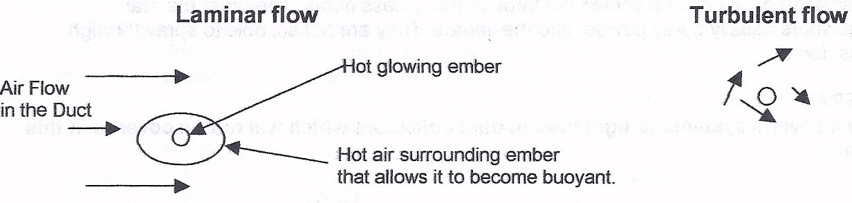
Transport of sparks through ducts. Referring to the sketch below, there is a glowing ember surrounded by some hot air which gives the sparks buoyancy. This spark and the hot gas associated with the spark can travel hundreds of feet in a duct. The ductwork is designed to give laminar (smooth ) flow. This is illustrated on the left. Spark suppressors are placed in the duct to change the flow to turbulent (coarse) flow, as shown on the right. This agitation or turbulence strips the air from around the ember removes the fuel (oxygen), therefore extinguishing and cooling the spark below ignition temperature.
For more on ... In-line spark arrestors (traps)
Prevention depends on eliminating the causes of ignition. Spark traps can change laminar to turbulent flow and extinguish any sparks in a duct. Design for proper dust transport velocities. Install pneumatic actuated duct booster to flush dust into dust collector. Use air jets to remove electrostatic charges on the duct surfaces.
For more on ... Duct cleaner - boosters
Spontaneous combustion in Pulse Jet Collectors can be prevented by pulsing the collector when the system is idle. This cools off the hot spots. For instance, brass furnace fires can be prevented by pulsing the collector every hour when the fan is not running.
Putting out fires can be accomplished by one of the following approaches: Cooling below ignition temperature, cutting off fuel supply, cutting off oxygen supply.
Water Hose and nozzles. This is an attempt to cool the solid fuels below the ignition temperature and to cut off the flow of oxygen to the fuel. It also takes away heat by turning water into steam. To boil one pound of water consumes over a 1000 BTU raising temperature of water by 200 degrees takes away less than 250 calories per pound. The steam generated can cause serious injury or death. The steam also displaces the oxygen in the air making it lethal but will often act as an inert gas to prevent oxygen from reaching the combustibles. Many dust collectors are equipped with spray nozzles. The hoppers should have automatic drains to prevent the water from doing structural damage. A 10 ft by10 ft collector with ten foot long filter bags can accumulate 40 tons of water if the sprays are not shut down or drained after the fire is extinguished.
Inert gas systems such as carbon dioxide or nitrogen gas are sometimes provided. Usually fire dampers will be provided to contain the inert gases. This will cut off the supply of oxygen to the fuel (dust and media)
Fan Operation during a Fire Whether to shut down a fan on a dust collector because of fire can be a difficult decision especially, if the collector is vented outside. Often, collectors are ignited at night and the smoke is not detected. The next morning the dust collector is virtually intact except the bags and dust have been consumed. For example a 10,000 SCFM collector removes heat at the following rate with inlet temperature of 100 deg. F. and various outlet temperatures:
OUTLET deg F. BTU/hr
150 500,000
250 1,000,000
300 2,000,000
400 3,000,000
500 4,000,000
550 4,500,000
With 1000 sq. ft. of cloth, the cloth would weigh about 100 lb and the dust about 50lb. If we assume a heat of combustion of 5,200 btu per lb, the BTU generated in a fire for this collector would be 780,000 btu. If we assume an outlet temperature of 450 degrees, it would take 30 minutes to burn itself out and the collector would probably not have damage to the tube sheet or cages. If the fan were turned off, immediately the temperatures would easily reach 1250 degrees and smolder for hours and the tube sheet and cages would be destroyed.
If the gas stream was re-circulated the decision is of course to shut down the fan.
Other fire extinguishing systems
Manual Fire extinguishers are usually either inert gas like carbon dioxide or inert powders. The gas extinguishers usually cool and put a layer of inert gas between the fuel and the flame. The manual gas extinguishers should not be operated through doors of the dust collectors as the displaced gases can be vented out through the access doors. The other manual extinguishers usually spray powder into the flames. They are not suitable to spray through access doors.
There a several other systems to fight fires in dust collectors which will not be covered in this chapter.
For more on ... Duct cleaner - boosters